Tape inside the shell holds the LED wiring in place and prevents light from shining through the thin spots of the locomotive. Had to add something to stop that as the shell is not fully light proof. If someone has a better way of stopping the light from shining through let me know.
Pop off the plastic cover on the top that covers the worm gear. Do this by inserting a screw driver under one side and twisting. Lift out the worm gear and drop the truck out. Don’t lose the square bronze bushing on the end of the worm gear shaft. You’ll have to un-solder the wires you have on the trucks as well.
Thank you for your assistance. I will get right to it. I just turned on the layout to program another locomotive and the decoder fried in this one. Not sure what the cause was. Burn spot was dead center right next to the plug. Plug was not firmly seated in the decoder. Going to go over it again and check for shorts.
Think I found it:
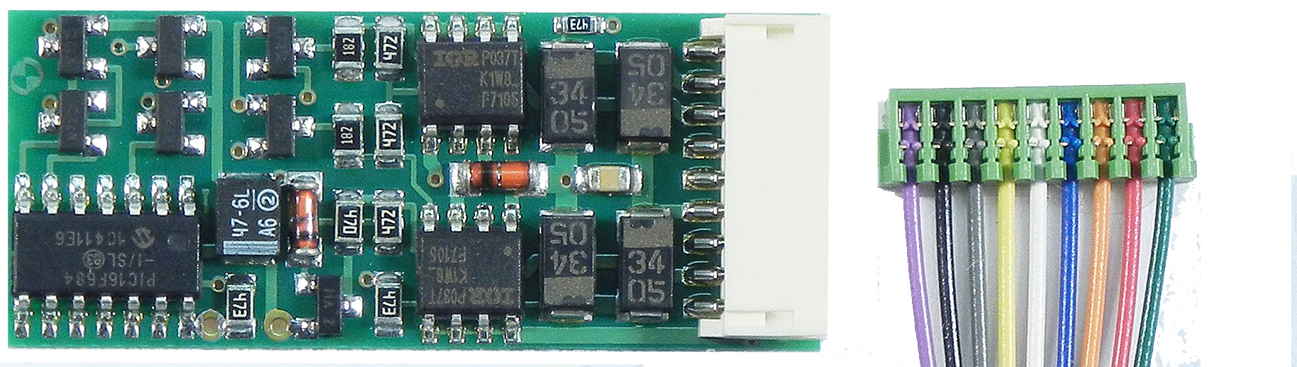
This is the D13SR, it is not the decoder involved, but it does show more clearly the components on the circuit board.
Here is the SRJ undamaged for comparison.
Red Circle is burnt component, which means I have a lighting short correct?
Your phone has failed you. Unless its the mobile verion of the forums thats preventing it, then MR has failed you. Also I think the last guy may have been poking at your strong believe in keep-alives. That isnt the issue here (or maybe it is [:^)]).
Also lesson learned here: Whenever you take the shell off a locomotive for any reason, when you put it back in service, start off on a programming track. It might just save you from replacing a decoder.
Conditions that the failure occured under:
DCC system: NCE PH-Pro 5amp
Locomotive location: On main power supplied trackage, no CB installed in system
Decoder: NCE D13SRJ
Locomotive: Athearn RTR GP38-2 programmed and operated with CV 29 set to 35 to dissallow DC operation, CV 29 was programmed on the main.
2nd Locomotive: Athearn Genesis GP38-2 DCC/sound
Description of event: RTR GP38-2 had previously been programmed and run on main line for approximately 5-10min. Locomotive shell removed and re-installed to facilitate relocating of DCC lighting and to attempt to correct leaning condition noted in previous posts. Main power was switched on for programming track purposes on a 3rd locomotive. Upon switching on the power, I noticed the RTR GP-38 take off running in reverse direction while the DCC/Sound GP38-2 was starting up. It ran approximately 5secs before smoke and acrid odor was noticed. Both Locomotives were removed from track at same time. Shell was removed from RTR GP38 and a burn mark in the indicated location was noticed, as well as scorching on the back of the 9pin plug recepticle. The plug for the harness was found not fully
I believe the burnt compoent is a filter capacitor based on where it is installed in relation to the four diodes. I would be looking for a short between your trucks and the decoder.
Runaway engines can usually be cured by turning off the DC enable aspect in CV29.
I searched around the locomotive with a multimeter and found a potential short on the bottom motor clip. I had already taped one end of the clip but not the other. Dont know if this was the issue. I can find no other grounds at this time. I plan to solder leads to the motor clips and route them though the shell under the dynamic brake fan (it is removable and has a dime sized hole under it). I will use this to check for continuity between the track and the motor with the shell on and no decoder present.
Mark,
I know about the CV 29 thing, but I think it was disabled. I didnt write the calculated CV 29 value down, so I cannot confirm this (decoder is dead). I also havent taken the time to go back and correct the settings on all of my locomotives yet. When I find they are acting strangely I do change CV 29 to disable DC operation.
With all due respect to the parties involved I, for one, would like to review the tutorial. However, I’m at a loss as to how to find the particular tutorial you reference.
If you don’t mind, a link would be very helpful to me.
With all due respect, I searched for your “tutorial”. And all I found was a reply from someone else’s post about how they were doing it wrong, and a list of what they should do. I followed the first response to my OP, and it took me to a video of an execellent model railroader doing a similar installation. I posted photos of the things I did to isolate the motor from track power. You have over 6000 posts on this website, but your best response is go look how I did it without any clue as to how to find it. Post your search terms in google if you dont know how to or cant copy a link with your phone.
Also you may have failed to read the part where I said the locomotive ran fine for 10min? Clearly this was a short caused by me removing and re-installing the shell. Dont know what exactly shorted, so I will have to dig through all of the wiring under the shell to find it.
Finally, I do not want your help davidmbedard, so dont bother sending me the link to how you did it.