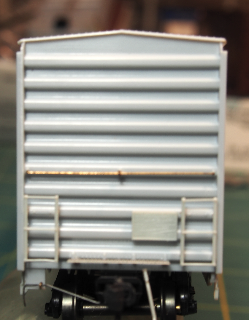
OK, it has to do with the end ladders. No matter which way I install them, they don’t fit into the holes (pegs fit in 2 holes, other 2 holes exposed. Between work, 2nd job and hockey, it might be until the weekend when I can take some pics. Maybe I’m not installing them correctly and you guys can see something I’m not.
I was going to type The messages under manage my profile turns red, but as I was browsing for what you might need to set (email notifications) I noticed a red message that was not visible during routine browsing in the forum.
I also get email notifications, but this reminded me I owe someone an answer.
OK gentlemen, just so everyone knows, here’s the goal:
While test fitting pieces, I noticed the end ladders do not fit into the holes completely.
Here’s the next snafu:
I believe the correct installation of the ladders according to the prototype would be with the long end down (last picture, left side).
As far as the exposed holes, am I missing something? Should all 4 pegs of the ladder be in the holes? Is there another way to install the ladders? I have Tamiya putty, should I fill the exposed holes under the ladder? Use styrene rod to fill the holes?
Your feedback is appreciated (no, I don’t plan on trying the bulged roof).
I was going to get back to you yesterday, but this POS Forum would not accept my login from my I-Phone, all I get is this giagantic error message.
But to answer your question I took a picture of the A end of my car by mistake, but you can see what goes in those upper 3 holes, I noticed in your first photo that you received 4 eye bolts, one goes in the middle top row, I glue that one first then thread the long grab through the eyebolt and glue the grabs into the outer two holes. On the B end the other large hole is for the brake wheel assembly.
It appears from your prototype photo that the bottom rung on the ladder is at the same level as the bottom grab iron on the adjacent side.
Regarding the empty holes, there is no evidence of them on DTI406’s photo. So he either didn’t have them or else did a heck of a good job eliminating them.
Don’t use putty to fill holes, its use is better-suited to filling surface imperfections. The best choice, in my opinion, is styrene rod (or strip if the hole is square or rectangular, although you could also drill it to suit a specific size of rod). I keep a full range of Evergreen rod on-hand specifically for filling holes.
Select rod about .003"-.004" larger in diameter than the hole, and if you don’t have the proper size available, drill-out the hole to suit what’s available.
Coat the end portion of the rod with solvent-type cement and use a suitably-sized brush to also coat the inside of the hole, then recoat the end of the rod again, and jam it into the hole. The solvent softens the plastic, and allows the rod to fit very tightly. Cut off the remainder of the rod, not too close to the plug, and let it harden - several hours, as you want it to be fully hardened so that it can be finished properly. When it’s fully hardened, use a sharp blade to remove any protruding material, then sand lightly if needed.
The advantage of this method is that the plastic rod has become an integral part of the plastic bodyshell, and can, if necessary, be drilled at any point in the repaired area. With body putty, attempting to drill partly in the bodyshell and partly in the putty, the drill will wander into the area of the original hole.
This same method is useful for mechanical connections, too, such as for truck retaining screws, which drop out because the threads in the hole have been stripped by over-tightening. Select slightly oversize rod, drilling out the hole to suit, if necessary, then, when the plastic has re-har
If either Wayne or Maxman had bothered to read my post in detail, I noted that all the parts were shown in Terry’s first pictures had places to be installed on the model.
THERE ARE NO HOLES TO FILL WITH PUTTY OR RODS EXCEPT the parts that are meant to be intalled in the holes.
I did read your posts in detail, Rick, but you’ll note that my reply was in response to Terry’s particular problem with the end ladders, as was that of Maxman.
Well, I don’t think I need defending, but if you had bothered to read all the posts you would have seen that a new question was asked that your detailed post did not answer.
Rick - sorry to hear of your troubles with the site. Problems with this forum seem to be commonplace. At least you were able to sign on, at some point, and comment. Yes, I’m aware the upper 3 horizontal holes are for the crossover handrail/grab and one of the eyelets are for the center hole.
maxman - I’ve been looking for reference points to line things up. I also notice the top part of the end ladders is almost even with the top of the tack board. Thanks for giving me another reference point to look at. As far as the proto, I believe this was a St Mary’s. I pretty sure it wasn’t a Railbox, as they used different end ladders (which came with the kit).
doctorwayne - thanks for the tips on filling holes, I appreciate it. If the holes/pegs didn’t line up, I had thought about just leaving them. Then decided against taking the easy way out, challenging myself to fill them. I’ll be off to the hobby shop this week for styrene rods. Plus, left unfilled, it would look undesirable when taking pics for Weekend Photo Fun [:D]
Thanks for the feedback, I’ll keep test fitting until I figure it out. Production is not far off.
Intermountain has been very helpful to customer inquiris. Maybe send them an email with the peg vs. hole distance dilemma and they may have a solution.