DCC or (not verses) DC

A scale mile - 61’ ?

My last layout, and the new one I am building have 420’ of double track mainline, or about 7 scale miles x 2 = 14 scale miles.

I have single blocks that are nearly a scale mile.

One of my 7 staging yards is 10 tracks, 22’ long each, or more than 3.6 scale miles of track in that yard alone.

Again, no voltage drop issues with soldered rail joints in DC - 56 years now.

Sheldon

Well, because my 81’ mainline wasn’t working well enough, we decided to try the store’s 15’ layout with the store’s system. Either way, the engines could not reliably draw the needed 1 amp or so of power without stalling (used 4 of my consignment engines that were at the store for sale). The store layout is Bachmann EZ track (snap track) also unsoldered.

When my buddy finds his 5 amp system (currently in a storage tote somewhere, and he was robbed recently) we will try my 81’ mainline with a 5 amp system to see if it makes any difference (I cannot afford to just go buy a 5 amp system at this time merely to test it).

My son’s long trains factually draw about 0.8 amps if there are 3 units, and at that point, in dcc, they begin stalling and intermittently restarting.

With the 18 volt-amp MRC dc power supply that just does not happen. I can easily run 4 diesels, with plenty of power for any train remaining (4 diesels in plain dc is about 50% of the available dc throttle).

I’m not saying that I 100% agree with NCE, and I’m an electrical relative dummy, but I can understand Stix and others having objections to what I was told. Also, it is true that the power drops I have may not be close enough together for dcc operation. The layout, again, was never designed for that, so that may be part of the problem.

More testing to come…

John

i’m curious to see a track diagram panel

i don’t understand what you think i don’t get

this is the first time you’ve mentioned the cab select buttons (kinda wondered) i understand that the logic to control the turnouts, signals, power the tracks based on throttle and any other I/O (e.g CTC) is implemented in the hardware under the bench which may have connections to other hardware, i assume implemented using relay logic as we’ve discussed before

i’m more confortable with a firmware, not a solid state approach. (a solid state approach might used digital logic ICs and mosfets)

i assume you can understand that the logic to implement the logic would be similar for each case. this could be implemented in separate code for each interlock, but instead of duplicating the code and modifying it for each interlock, i would use tables that capture the parameters for each interlock.

those parameters include the I/O pins for the devices (e.g turnout, signals) and description of the logic to control the interlock which could be just like an interlock, a series of (armstrong lever) changes where one could be blocked if some condition isn’t as expected (towers did it with mechanical devices)

below is a panel for one side of an 8 track passenger station. there are 75 routes thru the interlock selected by pressing a pair of buttons on either side of the route.

it uses the approach i describe above using a table to describe the switch positions for each route. (it is not an interlock) Since i&

Greg, I don’t have any pictures of my old panels, I have not built any new panels. For years I simply was not a photo bug, took very few pictures.

I do have a few pictures of the panels from a different version of my system built for a single track layout with no signaling. Each town uses a panel like this:

In this case there are two blocks separating each “town” which have a passing siding and other trackage. There is no cab assignment for the two passing siding tracks.

They get their power from the single track blocks based on turnout position. Turnouts are manually thrown but have electrical contacts to power relays that route the track power.

Some 20 years ago I designed this single track version and installed it on the layout of a friend, replacing a typical toggle switch DC system with teathered throttles.

The DCC users in our local group had no trouble using it and all said it was a big improvement over the previous DC system.

My friend passed away about 5 years ago, but last I heard his family still maintains and operates the layout.

The buttons in the photo are the same ones I use for everything.

Here is the relay board undr one of those typical towns:

This layout uses four Aristo throttles.

Poor photo but this is what the throttles and their base stations look like.

Here is a quick sketch of a panel for a simple interlocking with two crossovers.

So 4 primary blocks meet with the obvious available routes.

Obviously many int

Greg, one more important thought. We have talked about that interlocking on the NJ layout before. I will say, very impressive.

I have no interest in building anything that complex. I fail at any attempt to model real life track arrangements, and I don’t have that kind of room.

I could do it with my system, but it would be a lot, think one ice cube for each route.

I have one really complex interlocking on my new layout. Two double track mainlines come parallel to each other and a yard lead branches off one side.

You should be able to see it if you look lower center:

That is complex enough for my operating scheme.

Sheldon

thanks for posting the photos

look great. very interesting

Thank you.

A few more facts, maybe obvious, maybe not.

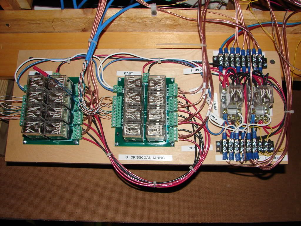
If a block is assigned to a cab, and you push a button to assign it to a different cab, it switches directly to the newly requested cab. So, you do have the personal responsibility to make sure the block is available. That is why there is occupancy indication on each tower panel and the dispatchers panel. But again, with a dispatcher, that is his job, not the engineer.

But this feature allows operators to not be concerned with turning off blocks as they leave them. The dispatcher will reassign them or turn them off as needed, or without a dispatcher the next operator can take the block when the occupancy is clear.

The reset button disconnects the selected cab, leaving the block completely dead.

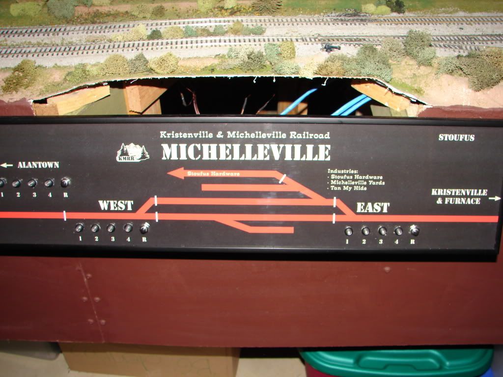
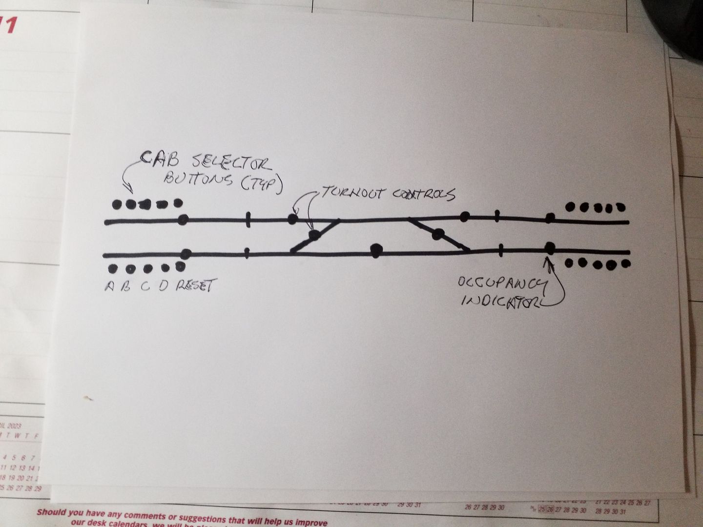
On system startup no cabs are assigned and all turnouts reset to their default “normal”.

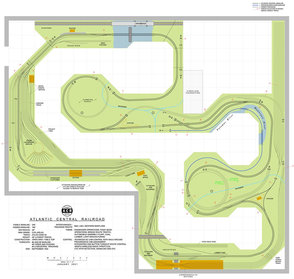
I am considering additional wiring that would lock out the turnout controls if a train is in the interlocking territory - just like the prototype.

Signals that are hard to see will be repeated on the tower panels or overhead occupancy panels as needed. But just like a real dispatchers panel, there will not be repeaters of the signal aspects there. Dispatchers only care where the trains are, how the route is set and who they gave permission to. Their panel tells them all that with a minimum number of lights.

All signals are “Absolute” or “Control point” signals - BUT, there will be approach signals half way thru each block that will give the appearance of permissive bock signals.

Not all signal aspects will be modeled, so in some places there will be a yellow aspect that you will never see lit. Or in the case of those approach signals you will never see the red lit. When their home signal is red, they show yellow, when their home signal is green, they show green.

Interlockings will be speed signaled with multiple heads typical to eastern practices.

There is no att

Sheldon–

It’s actually a really nice track plan that you have. Much less cluttered than some, and so a bit more simplistic, and I can appreciate the beauty of simplicity. It looks really good to me. Yet at the same time way more complicated than mine. Sure I have an 81’ run and a long siding, but that’s it. My goal was purely to railfan my own trains, and for much of the time the simple plan does exactly what we want it to do, and we are happy.

I’ve offered to my son that we could redo–re-scenic the layout however he wants, but he seems loathe to do that. Don’t know how else he’ll learn though…but he’d want floor to ceiling Rocky Mountains and that seems daunting at best.

Thank you John.

Large and complex are separate ideas. I prefer to use the space for broad curves, expansive scenery, and trackage to accommodate long trains.

Some aspects turned out just a little more complex than I was hoping for. Some of the hidden staging not shown on that drawing took a little more complexity than originally planned. But being able to stage lots of trains was an important feature. It will stage about 30 trains depending on their length.

Yes, the mainline scheme is simple, it models only one small city and some countryside. Minimum mainline curves are 36" with most more in the 38" to 42" range.

While my layout will have a reasonable number of industries, it does have a strong “railfan” or display theme to it. That was intentional. It has 5 “disquised” display loops for display running.

And most of the industries are off the mainline, like a separate ISL tucked into the layout.

Benchwork is started, and a pile of lumber is waiting for some of my tools to come home from our current work job. Then I have plans for a big construction push on the benchwor

Well, I particularly liked the use of the wye and I liked that it avoids the classic or not-so-classic “spaghetti bowl” aspect of model railroading. Far too many layouts go too far with too much trackage, and it appears that you are avoiding that while, as you say (tough to only see plan view) opening up the scenic opportunities. I like that the trackwork all looks like it has a legitimate purpose to it and not merely throwing more track down. So clearly there was some restraint evident in the planning. Good job. Don’t know that I’d ever get there.

I really appreciate the open country running where you were able to do it. That in particular is a really nice feature of the plan–the wide radii and extensive sections of double track.

PRR8259 wrote: “I have been informed by NCE that Kato track is junk for dcc operation and that I must remove and replace all of it. They want virtually every rail joiner soldered regardless of power drop location or bus wire size. They say soldered joiners are absolutely required for good dcc operation”

Like Humphrey Bogart in Casablanca who came for “the waters” but discovered he had been misinformed…

… you have been misinformed, as well. About everything you said above.

I’ve been using Kato HO Unitrack since 1988 on a railroad that gets run several times daily (using dcc from [earlier] the Roco z21 system and now the Digikeijs DR5000 system). No soldered joints. Just a few power drops. Runs just fine.

Thank you for your comments. I have only 3 power drops and that is indeed adequate for plain dc operation.

I did not say that I agree with NCE, and a few folks on another forum have basically called me the idiot in this because we are having problems here, so they clearly think it is all my fault.

To be clear, I had no problems operating in dcc until my son started trying to run 50 and 60 car HO freight trains with 3 locos. Then we started having real problems with intermittent stalling and restarting. I suspect issues with the entry level 2 amp dcc system, but that’s my opinion, and people who have the 5 amp systems have been very quick to tell me that I don’t know anything and am somehow mismatching locos so that they fail. Even going so far as to tell me sometimes the locos are wired to run backwards and asking me if I checked for that before running them together. Seriously, duh, and yes it really was said.

This is compounded by the fact that one manufacturer is releasing brand new locos with bad motors that fail. Oh–and believe it or not it is not Rapido.

Again thank you. I have some DCC experiance, but not with NCE so I can’t offer much. But I have always questioned the “extra power” some of these decoders can soak up. Seems like more features, more demanding sound systems, more lights and it all has to be “processed” after it get to the decoder.

Two amps does not seem like much given the nature of some of these locos.

On my DC system, each of my eight Aristo wireless throttles has its own 4.5 amp regulated power supply. I regularly run all powered ABBA lashups, or other four unit first generation lash ups like GP7’s, and sometimes triple headed steam with no issues.

I have never bothered to measure the current draw, but they are all DC with no decoders and simple constant lighting circuits. BUT, some do not have the most modern motors…

2 amps may simply not be enough.

I know the Kato track is a good product, I’m just not a sectional track fan. The number of rail joints being one concern.

Again, going back to age 10 when my father got me into this hobby, all my rail joints have been sol

Only started monitoring amperage when we began having problems and specifically when motors began failing. NCE controller reads out amps if you get the correct setting.

Have literally watched an engine go from running well (out of box perfectly for few hours) and only drawing 0.30 amps in dcc with a train behind it to drawing as much as 0.89 amps, running hot and intermittently, in as little as 20 minutes flat. At that point I know the motor is toast. The engine will still run, but not correctly and not at the same speed as its (exact match, same loco, same product run, different road number) brethren. If operated in plain dc, they also will not run correctly but surge (speed up and slow down without throttle setting changes).

It is not the Athearn units that are failing.

Most current run locos I have tested draw only 0.3 amps or less, at speed step 28 of 28, with a full train (say 20 cars) behind them, all lights and sound on. Below speed step 28, the current draw will decrease as you slow down, to as little as 0.03 to 0.06 amps at idle.

Will experiment more when buddy and train store owner locates his 5 amp system.

Thank you.

A lot of DCC sound locos draw a bit more power and do not pull as well, to offset this modern rolling stock rolls freely and a lot are lighter, it is all trade offs.

Roll freely and intentionally lighter? Don’t get me started…

0.3 amps with a full train and all lights and sound on, at full speed, is awesome even compared to old Kato engines. It is significantly less amperage than back in the day. They have many more lights than back in the day.

I even have a brand new BLI Paragon 4 SD40-2 that draws only 0.06 amps at idle with sound and lights on. That is way better than diesels from years ago. Athearn units can get down to 0.03 amps!

Today’s freight cars that have rotating roller bearings are anything but free rolling.

It is long past time for someone to extend the current discussion on truck physics and truck-tuning ‘best practices’ to cars with rotating endcaps. Here are a few initial thoughts for whoever does that.

The ones I’m familiar with have coned axle ends, with a wirelike thin extension through the sideframe on which the little cap is pressed.

Under ideal construction conditions, this should have the same guiding and location characteristics as the double-cone pointed-axle construction, with a slightly larger effective contact patch just inboard of where the wire end commences. This immediately implies that the truck-frame alignment and spacing would have be be highly precise, as there is less freedom for the wheelset to move side-to-side within the constraint of the larger-angle coned recess for accommodation. It also implies that slightly greater clearance at and through the sideframe for the ‘wire end’ needs to be provided, for the cones to do their work effectively, and that the caps be carried slightly outboard of the truck frames when pressed on – perhaps with a guide tool similar to that for Bowser valve gear to get the spacing correct without trial and error fiddling.

If you used a truck tuner to machine the active part of the cones in the sideframes, it might be necessary to fine-adjust the sideframe lateral spacing to the new profile. I am not sure a typical gauge for this would be inexpensive to make.

Now, on the other hand, anyone over the age of about 50 will be familiar with the operating principle of Hot Wheels cars, which involves a Delrin/acetal bushing pressed into the wheel bearing on a thin wire axle. It would certainly follow that if the sideframes were tooled or machined to insert a thin-contact version of this type of bearing, if not indeed made of the appropriate material with the a

I used to be an alumni member of my college’s model railroad club. Even though their layout wasn’t very large, they constantly had problems with the circuit breaker going off because they didn’t have enough power to run even one train with three engines. When I went with DCC I purposely over-built the layout. It’s not huge - largely a shelf layout around three walls of a pretty large basement - but I have the main controller in the middle (CVP) and two “zonemaster” boosters, one on each end of the layout, each providing 7 amps of power.

Under-estimating power requirements is quite easy. Thanks to everyone who suggested not being cheap on feeders or placing them too far apart from each other. DCC does require more patience and understanding, but a thing of beauty when it works.