Rich, thanks. That’s what I thought that you were not talking about model train layouts. I think I’m going to be glad that I went with the solid especially with the suitcase connector method versus soldering.
Thanks again.
Gary
Rich, thanks. That’s what I thought that you were not talking about model train layouts. I think I’m going to be glad that I went with the solid especially with the suitcase connector method versus soldering.
Thanks again.
Gary
Stevert, your right I have a tendency to over think everything. I’m just intimidated by the complexity of DCC and I would have never have thought that I could use terminal strips. I look at some of the wiring shown in the books and websites I’ve reviewed and these multiple wires going from various devices to large and small terminal strips and it just becomes hard to understand what it is doing and what its trying to accomplish. It’s like reading Larry Puckett’s DCC corner explanations of these and other devices and I end up rereading them over and over and many times not understanding exactly what he’s saying.
I think for any newbie to DCC it really is not easily understandable and for most people who have been around DCC for years its like second nature.
Thanks again for claryifying and for all your help.
Gary
Renegade, thanks for your information. I did look at the DS64, but not the SE8 for turnout control. I think I was tending to go with the DS64, but then I saw this NCE Switch8 that talks about controlling 8 switches (I think the SE8 also does 8 and DS64 four if I’m not mistaken) and that it had this optional circuit board “Button Board” for adding push button control. I was thinking having push button control as well as control through the throttle would be helpful. My only concern is I never know whether I should stick with Digitrax only devices as much as possible to eliminate compatibility problems or if its OK to use others (like the PSX-4 instead of the BXP88).
I’m starting to get a little worried now that I might have bought the wrong size wire for my feeders as your and others input have mentioned you use 22-24. I hope I can use the over $100 of 20 guage solid I bought (in shipment) without having problems with soldering to the code 83 rails. I finally received all my track I ordered and wow not much room in the rail for the wire.
As far as block detection, signaling and accessory bus, I haven’t given this much thought as I just want to get the trains up and running as simple as possible. Maybe down the road I’ll want to do this, but I figure this project is going to take me a few years (especially with scenery, buildings, etc.).
Thanks again for your insight and help.
Gary
Randy, I bought a wire stripper and it has a range of 10-20 gauge wire nicely numbered/slotted for solid and strand and used it just to see how it would strip the 14 gauge solid and for the first time in my life I was able to get a clean and easy strip. Wish I had one of these when I was rewiring an extension cord I cut with my hedge trimmer.
This is what I’m saying about having a hard time understanding DCC. Your comment about diode drop and transformer type detectors is like Greek to me, but I know you were really talking to the other guys who have been around DCC for years.
Again, thanks again always for your help.
Gary
The #20 is fine for feeders.
The DS64 also has connections for pushbuttons - bonus is unlike non-Loconet devices, it actually reports back the change when you use the buttons. I really am not a fan of operating turnouts from the throttle - no brand of DCC system makes this particularly conveninet, you always have to switch to some sort of ‘accessory’ or ‘switch’ mode, select the address, set the position, then switch back to train control to resume control of your loco. So buttons along the fascia are an absolute requirement for me.
I used servos on my last layout, and will use them again on this one. I used Tam Valley’s servo controllers, which have buttons and LEDs plus, depending on which one you get, are also DCC decoders so they can be controlled from a throttle or JMRI.
Layout before that, I did have some NCE Switch-Its, that’s a 2 turnout version of the Switch-8, which wasn;t available back then. I’m not a fan of running long wires everywhere, so controlling 2 at a time per board was just about perfect. For a yard or an area with a concentration of turnouts, the Switch-8 is more economical, but at a crossover somewhere in the middle of the main, having 8 when you only need 2 (and really only 1 - a single output on these can drive 2 Tortoises, or you can use linkage so only one Tortoise is needed to operate both turnouts of a crossover) might mean running long wires to reach another 6 switch motors.
One thing I noticed about the Switch-It, the drive voltage is a lottle low. Tortoises are specced to use 12V, but they are a bit noisy at 12V, closer to 9V seems to be a sweet spot. This is perfect - you can wire LEDs in series with the motor wires to give position indication, no resistors are needed, and the voltage to the Tortise ends up being 9-10 volts if the supply is 12V. On the Switch-It, it’ already driving with a reduced voltage, so putting the LEDs in series witht he motor made them a bit too slow. Bu
Randy, thanks again for your insight. I think your kind of hinting to go with the DS64 and perhaps that’s what I should do. Not sure about everything your saying, I tried reading up on the DS64 and I see where you connect for the push buttons, but not sure about LEDs. I noted that all return wires for the push buttons go the the +COM single connection (do four #20 or much smaller wires fit into this connection?) Are these LEDS separate connections from the push buttons on the DS64 or are they wired to the Tortoise or does the push button have a built in LED?
My layout will have 23 turnouts (one being a WYE turnout, but not used as true WYE setup). Most of course are at both ends of the small yard or leading to the yard or really its more like 3 and 2 sidings off the main tracks. Do you use the #20 wire to connect the Tortoise to the DS64 and to the push buttons?
I’m not sure about computer hookup and JMRI use. I probably will not have wifi in the steel building thats about 30’ from the house, so I’m not sure about using a computer, other than to update firmware.
I think the main point your making is the LocoNet connection on the DS64 gives me feedback that I wouldn’t get with the Switch 8 without additional hardware.
Thanks again, you’ve really helped alot.
Gary
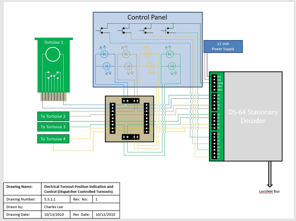
The DS-64’s do not a have seperate output for LED’s. What I do is wire a set in series with the Tortoise. The tortoise motor acts as the resistor. You can use two back to back (parallel but opposite) or a bipolar (two-lead) LED in series with the tortoise. This is a quick way of showing turnout direction. The other option is to use the contacts on the Tortoise switch machine to show turnout position but that is a lot of extra wiring.
Here
Renegade, wow, I really appreciate your diagram and detailed explanation. I can see that DS64 is the way to go, especially as you indicate for future signaling. As a non-experienced DCC and not very electrical knowledgeable person, if the protoboard daughter is not something that I can find already made for this purpose, I’m not really sure if I can attempt this hookup. Also, I really don’t understand your “K” and arrow electrical symbols on the control panel. I assume these are your LEDs, but not sure how I connect these and really don’t understand your statement to use "two back to back (parallel but opposite or a bipolor (two lead) LED. I assume that one of the K symbols represents a second LED parallel so that depending upon which way the switch motor is thrown one light would represent open and the other closed. My experience with LEDs is XMAS string lights, but not how to wire them.
I assume that if I don’t use the LEDs, that I can wire the push buttons, Tortoise and DS64 without the protoboard, but I can see how the LEDs would be really helpful to avoid turnout shorts and derailments.
I’m also a soldering newbie, so I assume the wire connections to the push buttons have to be soldered and I assume the LEDs also. This is the area I’m most dreading, as every type of device I’m hoping to use will have screw connections. One of the reasons I’m definetely going to use the snap or other type connector for the Tortoise so I don’t have to solder directly to the device.
Again, I really appreciate your help!
Thanks, Gary
DS64 has screw terminals, but you will have to solder something. You don;t NEED a custom board sitting in the middle - the wires from the buttons go to screw terminals on the DS64, and for the LEDs, the wire runs from the screw terminal of the DS64, but then has to be soldered to the LEDs, and another wire soldered to the opposite terminal of the LEDs, which then goes to the screw terminal of the Tortoise connector. The second wire to the Tortoise goes between the Tortoise and the DS64.
Thoise are’s K’s, they are a text way od drawing the symbol for an LED. LEDs and regular diodes only allow current to flow in one direction. The easy way to remember it is that it goes from positive to negative, and the ‘arrow’ in the symbol shows you which way. The Tortoise works be reversing the polairty of the DC power to make the machine move one wya or the other. So with two LEDs connected together but opposite as shown, one will light up when the Tortoise moves one way, the other will light up when the Tortoise moves the other way.
–Randy
Good Morning Gary,
you are correc that the K symbols are the LEDs. A Light Emitting Diode is sym
Randy, thanks for the clarification. Your and Renegade’s clarifications makes it more understandable.
Thanks again, Gary
Renegade, thank you for the additional clarification. Your explanation about connecting the short leg of one LED to the long leg of the other LED and the opposite for the other leg clarifies how these should be wired. I believe your also saying that no wire goes between the two legs of the same LED. I assume I have to have a continuous wire running from the Tortoise to the first LED short or long leg and solder that, then another wire from that LED leg to the other LED opposite long or short leg, solder that and then a wire from the LED’s other leg to the opposite leg on the other LED and from there to the DS64. Or, do I make one continuous wire from the Tortoise to the DS64 (I think that would be similar to the way I have to wire the toggle or push buttons for the +COM connection) and solder separate wires from that wire to each leg of the LEDs? I understand there is also one continuous wire directly from the Tortoise’s other connector to the DS64.
Thanks for all the tips on the soldering. That’s one area where I’ve been reading up alot about, so I understood the type of solder, flux and even some of the recommended type soldering irons. I actually ordered 0.023 dia. solder based upon someone’s book or website recommendation. It hasn’t shipped yet so I might be able to cancel and reorder the diameter you use, but I think it was also recommended for the difficulty of wiring to the Atlas turnout frogs. I was hoping that the soldering to newly purchased track would not require wire brushing, but if that is recommended or using the rubbing alcohol (the latter had not been mentioned by anyone else that I’ve read up on so that might be the easier or better method for me).
Yeah, I definitely need to practice my soldering before I mess up things. One question I do have that I really haven’t seen a recommendation for or warning not to do, but if I solder my feeders to the rail joiners (since they should be
You would solder the long lead of one LED to the short lead of the other. Then solder the other 2 free leads together. Fit the LEDs in yous control panel - depending on what you are using for the penael, there are some simple plastic bezels that push in to a thing panel to hold the LED, or there are fancy metal ones, and everythign in between. This is purely mechanical, to mount the LEDs.
Then you run one wire from the DS64 output to one of the joined sets of LED legs. Then run a wire from the other set of joined LED leads to either pin 1 or pin 8 of the Tortoise. Finally, one more wire from the other output terminal of the DS64 to the unused terminal of the Tortoise, either 1 or 8. If the positon of the turnout and which LED lights up are wrong, swap the wires on pins 1 and 8 of the Tortoise.
–Randy
Randy, thanks again for clarifying.
Enjoy your day and stay healthy!
Gary