xx
xxx
Paul Milenkovic,
Very interesting point you have on the “Red Devil” and high exhaust pressure relief into a feed water heater system.
This observation is seconded by Ralph Johnson who was design engineer for Baldwin Locomotive Works in his book The Steam Locomotive.
Ralph saw one of the truely dynamic possible design factors of “poppet valve gear” was the separation of intake and exhaust valve events by removing the symetry of movement Walschaerts valve gear applies to both intake and exhaust piston valve events.
The exhaust valve event cannot be optomized because this would adversly effect the intake event. At close “cut off” valve settings - when Walschaerts would become most effective - it suddenly then ceases to become effective because of the compromise the intake event forces upon the exhaust and the exhaust upon the intake. Walschaerts valve design cannot achieve what becomes possible with steam locomotive power development.
Poppet Valve Gear design - owing to the use of camshafts - on the other hand has a unique ability to have taylored separate valve event for both intake and exhaust.
This fact plus the possibilty internal steam passage streamlining for intake and exhaust passages without the obstruction of the Walschaerts “valve piston” allows ever increasing possibilties of performance in reciprocating steam locomotives.
Automotive type intake and exhaust ports with poppet valves similar to gasoline engines are then a possibility with railroad steam engines.
Here is the Red Devil application of tapping off of high pressure exhaust for feed water heater and condensing effect. Additional added advantages of reducing exhaust back pressure and exhaust nozzel restriction ushers in many other possibilities for firebox and boiler draft and front end smoke box design then become available with this arrangement. &nbs
You need to look much more carefully at the detail history of poppet valve design and development in the United States. There is more to effective steam distribution than better-flowing valves – dead space, routing of steam flow in the tracts, and compression control being three. That is before you get into spring return, sealing under a wide range of temperatures, problems with drifting, etc. Note that Wardale and the 5AT organization both have come to prefer piston valves to poppets on locomotives that have to be maintained at lowest cost in regular service, and have explained their reasoning in some detail.
There are also approaches for compression control (simple, like Okadees, or more complex like Jay Carter’s approach for steam automobiles) that work just fine for the practical benefits and don’t have the ‘nightmare box’ cost and maintenance issues that OC or RC poppets do. Trofimov valves, as improved by Meiningen, (or Wagner bypass valves) give much of the improvement in drifting that poppets provide.
Where poppets are most valuable is for high horsepower at high speed (see the two variants of the Lima-modified K4 setup). But not much of a locomotive’s time is spent in that range. Meanwhile, compare the performance difference – at the cylinders – between Wardale’s double long-lap/long-travel articulated piston valves, with ‘diesel-style’ rings (driven by Baker gear with Multirol-type bearings on all pivots) and a typical Lentz or Franklin setup.
Wizlish,
Glad to see you chime in on this discussion, but when did throwing out a bunch of technical names and vague comments constitute a legitimate retort?
Reading your text - I found we are in agreement on several points - first that when it comes to overall horsepower production the “poppet valve” arrangement is probably the top producer.
Second that the geared “poppet valve” designs from the 1930’s and 40’s were complex, expensive, and breakable - these designs however are over 75 years old. I cannot come to believe that a modern engineering and computer design “poppet valve” concept could not overcome all of these limitations cost effectively.
Lets speak of general engine valve designs -
-
“Sleeve valve” as used in early automobiles and in Ricardo’s work.
-
“Rotary valve” as used in some internal combustion motor designs such as CSRV.
-
“Piston valve” as used in most steam locomotive designs and potato guns.
-
“Reed valve” as in two stroke interal combustion and modern compressors.
-
“Poppet valve” from internal combustion and reciprocating steam.
I for one cannot think of any other common valve designs applicable to power producing machinery and “poppet valve” is the top choice for design efficiency in all modern engineering.
I do not think any designer would choose “piston valves” for reasons other than tradition and abject simplicity. Possibly the Wardale articulated design with Baker action was a workable compromise for commonly accepted maintaince schedules Wardale was confronted in maintaining Red Devil. The multi roll bearings and diesel piston rings on piston valves is novel considering the problem with “carbon sticking piston valves” that high demand situations created (such as when Pennsy borrowed a N&W 600 for tests and stuck the valves).
The above post suggests that steam would have prevailed if the diesel-electric wasn’t introduced until after additional improvements to steam were made. That would assume that the diesel-electric was a static design to which improvements could not be made. The fact remains that steam is dead or dying both on land and on sea.
8,300 posts! Impressive!
CSSHEGEWISCH this observaton is by no means a fact.
It is held that the internal combustion engine thermal efficiency is on the order of 25-30%, and the external combustion reciprocating steam locomotive thermal efficiency on the order of 10-20%. These basic statistics are often given. Steam powerplants, however, have achieved thermal efficiency as high as 40-50%.
Expense of crude oil per barrel has risen from $1 to 2 dollars per barrel in the 1940 and 1950’s to todays high of $128 dollars per barrel. The steam locomotive was challenging the cost efficiency of diesel electric at the time diesel was adopted as America’s prime mover in the 1950’s. Today serious consideration is given to steam power as an alternative power source.
While more efficient in design the cost of diesel operation vs steam operation has been challenged by the attempt to produce steam locomotive ACE 3000, and by such enviornmental engineering groups as Coalition For Sustainable Rail to build an ATSF 3463 alternate steam prototype locomotive.
While the recent “shale oil boom” has lowered oil prices again the wide availability of cheep natural gas has caused diesel engine designers to think towards converting from diesel oil as a heat source to running on natural gas instead - supplied to the locomotive diesel engine by tank car bottle tenders as a viable option.
The consideration of steam power has merit for discussion on this site for historic purposes if not as as potential source for the engineering modern power.
Wislish has a great technical engineeing background he has been encouraging me in private e-mail to speak about the Rankine Cycle. I wish he would do so instead because with his advanced mathmatical background he really does a better job and has greater insight into this type of discussion.
Sometimes you have to provoke Wislish to get him to come out of his study
A couple things.
The 10-20% thermal efficiency of steam locomotives is perhaps the theoretical efficiency of what can appear on indicator diagrams with a 100% efficient boiler, mechanical transmission, perfect valves, no wall condensation loss in the cylinder, heat loss from uninsulated or poorly insulated firebox, boiler, steam pipes, valves, and cylinders. Wardale gives figures that year-in year-out efficiency can be as low as 3%.
The Brown studies suggesting that steam locomotive economics were more favorable than generally understood assigns a value that steam, on average, used 6 times the BTUs of Diesel locomotives. Wardale gives some figures suggesting that the fuel consumption of steam could be even higher than that.
My thinking is that using all of the Chapelon/Porta/Wardale/Girdlestone improvements to the Stephenson-type steam locomotive without going to “exotic stuff” like turbines, condensing, water-tube boilers could improve steam to 3 times the BTUs of Diesel, making steam competitive with coal-to-liquids and burning that in a Diesel instead of the coal directly in a steam locomotive.
I have read the white papers on the Coalition for Sustainable Rail, and here are my impressions. No disrespect intended, but I think this group is very much like the ACE 3000 project in motivation and intentions. What I mean by this is that they are railfans and steam enthusiasts (not that there is anything wrong with that!) who are carrying the environmental banner as a justification for doing work on “modern steam.” They are simply not a group of environmentalists who got up one morning and though, “Gee, last bring back the steam locomotive to burn biomass!”
Furthermore, the Santa Fe Hudson is their version of the C&O Northern in the ACE 3000 project. They don’t intend a 1940’s Hudson to be the “final form” of their high-speed passenger solid-fuel burning passenger loco. Rather,
Doc, ya gotta remember that steam plants get their high efficiency in ways that cannot be packaged practically on locomotives. They rely on very steady and continuous operating conditions, they usually have lousy turndown ratio (and in many cases turndown actually leads to boiler and refractory damage as the combustion gas paths etc. change!), they do feedwater heating with multiple bleed stages on the turbine, they use radiant superheating and exhaust into a substantial vacuum with enormous plenum volume…
The Carnot cycle represents the absolute maximum efficiency that can be used by an engine that uses heat to expand a gas and push something to do work – a piston, a turbine blade, etc. That neatly corresponds to the maximum work that can be done with, say, an internal combustion engine, which generates its combustion gas entirely within the cylinder. An external-combustion system, though, can follow the Rankine cycle, which looks at the most effective way of using the heat to produce a given amount of work practically – can exhaust heat be used to preheat water, or air for combustion, or can steam at higher temperature preheat a cylinder to reduce wall temperature when steam at lower temperature is admitted for power, for example.
The thing is that many of the ways in which heat is most effectively transmitted from combustion to work involve expensive, or heavy, or bulky, or complicated systems, many of which do not take kindly to the environment encountered by working steam locomotives that have to earn their bottom-line keep. Perhaps nowhere is this illustrated better than condensing, but there are reasons why
Sure, if you are talking about a 1960’s era gasoline engine. Many modern car engines are in the 30% - 35% range. Toyota has some engines that are up around 38%. Modern turbo-diesels are easily in the 40% - 45% range, while large marine diesels are 50% to 52% thermal efficient.
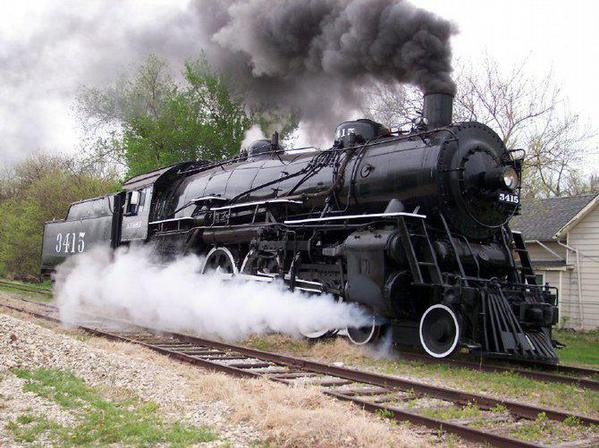
I just finished watching “Dreams Do Come True: The Restoration of Santa Fe Railroad pacific Class 3415” and it does indeed have the Elesco FWH mounted under the smokebox on the pilot deck.
The Elesco, Coffin, and Worthington feed water heater systems consisted of water pump or pumps - one sometimes two - and the heat exchanger. The pump was often on the pilot deck but sometimes on the side of the locomotive - the early ones were huge. The all important heat exchanger - which was of the “open type” or “closed type” - was usually ahead of the stack. The “open type” mixed exhaust steam with the cold water feed into the boiler, the “closed type” did not mix but used a system of hot pipes to heat the cold boiler intake water.
Both of these systems were common to many late ATSF steam locomotives like ATSF Hudson 3463 in Topeka KS - Worthington “open system” with water pump on the pilot deck - and many other railroads.
An examination of ATSF 4-6-2 Pacific 3415 does indeed show what appears to be the Elesco bundle - “closed system” on the pilot deck. Can’t say I have seen many in this location. Looks good though!
Doc
Hey Doc, you learn something new everyday, eh?
Ye gods, just the kind of discussion I love, and I have been missing it completely! Let me take up some of the points with a bit more detail. I keep thinking that because I’ve seen technical detail, it’s self-evident to others with serious interest and knowledge of steam practice… that’s a dumb assumption. As my great-grandmother used to say, ‘ignorance is not stupidity’. (Except when it is ignorance as shown by me in assuming everyone knows the esoteric stuff!)
Much of the effective limitation was solved in between the PRR efforts in '47-'48 to fix the T1 problems (many of these, like better centrifugal casting of the valves, were never implemented) and the system on ATSF 3752 that is described in Vernon Smith’s One Man’s Locomotives. The ‘catch’ is that even the simplified used in Franklin type D (which uses a kind of wire-drawing effect to produce the effect of cutoff as speed increases) has complicated gears and shafts that require close alignment and careful maintenance. With the advent of comparatively cheap CAD/CAM, many of the objections to designing and fabricating the ‘nightmare boxes’ are reduced. But there is still much more involved in providing all those valves and seats and springs and cams when the alternative is a (comparatively) simple articulated, multiple-ring long-lap long-travel piston valve (or Willoteaux valve if you need the equivalent of multiple ports opening in parallel)/ driven by a simple pin-jointed linkage like Baker gear.
[quote]
“Sleeve valve” a