What is a steerable truck? How does it work?
If you look up ‘radial truck’ it’s the same basic principle; Trains Magazine had a pretty good early explanation circa 1995 that I believe they provided free as a ‘reprint’ on the Web for many years and perhaps still do. The principle is also extensively discussed in Lionel Wiener’s book on articulated locomotives.
The basic principle is that the leading and trailing axles of the truck itself have the ability to pivot so they can be better aligned as tangent to the line of the rail even in a sharp curve, and are then ‘steered’ by a system of levers so that the leading axle is correctly aligned relative to the truck frame.
Note that in the case if the later EMD HTCR-II trucks that the actual center less pivoting of the trucks relative to the frame can be actively controlled with elastomer-sandwich shear springs, which also give good lateral compliance.
The GE equivalent has those heavy outside levers that look like hinged boards. There is a patent that shows and describes how these are supposed to work. CSX has a fairly great number of engines with these, so they must be effective enough to preserve.
One practical effect of the ‘usual’ steering on a C truck is that the effective rigid wheelbase of the truck goes to zero. You can still hear a little flange squeal on short instances of excessive curvature but the usual kinds of curve noise are relatively absent.
There are designs for steerable-axle four-wheel trucks, although they do require somewhat more design complexity to work as intended. In most North Anerican practice a little additional controlled lateral provides most of the ‘benefit’ that steered axles would at the speeds involved for B trucks.
I’m sorry Dr. Track (buslist) is no longer with us, as he could have provided much more detailed information, including true best pr
Someone please enlighten me regarding terminology About track curvature.
This I how I understand it:
A 300’ radius curve, if continued around 360 degrees to form a circle, that circle would have diameter of 600’. Which would be a very tight railroad curve. Correct?
A 5-degree curve, in the space of 100 ft, will change direction by 5 degrees. Correct?
Shenandoah Sub reopened.
https://www.facebook.com/pete.darmody/videos/pcb.2720234538037870/10217066029871750/?type=3&theater
An old RR surveyers eyeball says this is a 2-3 degree curve. Probably train handling is responsible for this one.
I suggest you scale off of an overhead view, as I did:
Using Googlemaps satellite view, I zoomed in until I was on the 50 foot scale. On the screen, the radius of the curve is approximately 5 inches. The length of the 50 foot scale is 3/4 inch.
5 / .75 = 6.7 units
Since each unit represents 50 feet, the curve radius is:
6.7 x 50 = 335 feet
As I said, this is an approximate method, so carrying accuracy to 3 decimals is pushing it. The radius is roughly 300 (one decimal place). It is certainly not over 450 feet. And certainly not under 250 feet.
But it is nowhere near 2-3 degrees, which is approximately a 2000-3000 foot radius.
If you care to go through my method yourself and point out my error, I would appreciate it. Nobody likes to be wrong.
Ed
PS: I have since scaled off of a USGS topo map, and also got approximately 300 feet.
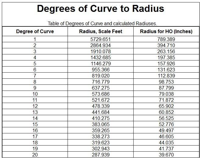
There have been two functionally equivalent definitions, historically. One is the radius required to sweep 100 feet of curve in N degrees, the other is the radius required to sweep a 100-foot chord on a curve N degrees. For all intents and purposes, at least with respect to 1:1 scale railroading, they are the same measure. In general, you can use the formula D= 5730/R where R is in feet and D is in degrees with R>300 feet putting the difference between the “chord method” answer and the approximation less than 1/10 degree, less than 1/100 degree when R>800 feet.
DC or Mudchicken can illuminate how surveyors use this to stake or measure curves, and if you are really masochistic, you can ask about horizontal spirals into and out of curves (or why passenger cars don’t jerk you out of your seat when going into a curve).
Here is a handy degree-radius conversion chart:
Ed
Correct on the first.
On the second: For railroads, the 100.00 ft. is measured on a chord - the actual arc distance is a little more (depends on how sharp the curve is).
For highways and other general civil engineering applications, the 100.00 ft. is measured along the arc/ curve (the chord distance is a little less).
(There’s a difference between 100 and 100.00 feet, so I’m respecting that.)
Above applies to North American practice (and likely S. America, too); not familiar with the details of how it’s done in other parts of the world.
Separately - sometimes a good way to figure out the degree (radius) of a curve is:
-
Extend the two tangents to where they intersect near the middle of the curve.
-
Measure the angle with a protractor - angles are not subject to the same kinds of scaling error, just interpolation.
-
Measure the distance from the same points as you meaured the angle with the protractor. This should be measured along the curve, not the ‘shortcut’ (chord) between the ends. This is subject to scaling error, but as a much smaller percentage.
-
Divide angle from 2 above by the distance from 3 above to obtain the angle turned in each 100 ft. = degree of curve. NOTE: This is crude enough that it doesn’t matter whether you want the chord definition (railroad) or arc definition (highway) - it’s not precise enough to differentiate between them. Said another way, it’s approximate for either one.
-
Divide 5,
I did a web search under several terms and came up with zilch as well. That would be the ultimate resource, however.
Thanks, Paul.
If I understand correctly, “degree of curvature” is how tight a curve is. Is there a term for simply how much (in degrees) a single curve changes the direction of the rail line (regardless of the radius)?
Which begs the question: are any curves in railroading either increasing-radius or decreasing-radius ones. (Both of those commonly exist on roads and auto racing tracks.) Or are they all constant-radius curves? Most would be connected by tangents; but, say, a crossover would be two curves end to end, one a left and the other a right, or vice versa.
Most/all mainline curves include increasing-radius and decreasing radius curves. They are called “easements”.
A crossover track is NOT two curves end to end. The curves are all incorporated in the closure rails, which run between the points and the frog. Between the two frogs, all the track is normally straight.
Ed
Thanks, Ed. I’ve learned a lot today.
Regardless of increasing or decreasing radius of the curves - the speed restriction for that segment of track will be set by the requirements of the sharpest of the curves.
As a race driver you want to maximize your speed to the limit of each segment of a curve - no matter if that particular segment is increasing or decreasing in its radius. On the railroad one speed fits all and that limit applies to the entire length of the train.
Tyhe answer to your first question is “central angle”, often called in shorthand the “delta” in my experience here on the East Coast - may be other terms for it both here and elsewhere. It’s one of the 4 best mathematical values of which any two will define a curve - the other 3 being degree of curve, radius, or length - either arc or by chords (to a lesser extent the tangent, long chord, or external will also suffice).
Low speed curves with little or no superelevation are often nominally a constant-radius curve, although as a practical matter the stiffness of the rails imparts a little spiral at the ends.
Spiral is the universal term for the increasing radius and decreasing radius curves, which are used mainly for higher speed tracks, those with sharper curves, or where a lot of superelevation is needed. Usually the radius at the beginning of the curve is infinite = tangent, then it gets progressively sharper until it matches the constant-radius part. Aside from easing into the curve, one important reason is to be able to gradually increase the supelevation from 0" on the tangent to the proper value in the body of the curve. The details of all this are beyond the scope of this forum, and take up chapters in books on route or track alignment/ surveying and professional papers.&nbs
I tried to determine the radius of the curve from a large-scale (1" = 20’) print of it from Google Maps Satellite View. However, there’s the apparent kink I noted previously just before leaving the bridge in a SW directon, and then a flat spot just after arriving on ‘dry land’ opposite the angle in the adjacent Appalachian Trail walkway (which is to the SE). Those are likely distortions from Google Maps, not real-life track configurations. As a result, I would not put much faith in any curve radius determination based on the Google Maps Satellite View.
That said - and having read a little about the history of track relocations in this area over the years - as I said before, it could be 12 to 15 degrees, and I’m now leaning more towards the 15 - 16 degree range. Although it may be termed a “main track”, it’s more like a secondary/ branch line. Such curves - while certainly not desirable - may be a result of history and a present-day fact of life for the railroads that have inherited them and must still operate over them today.
- PDN.
References on the history of the Harpers Ferry bridges:
http://www.wvculture.org/shpo/nr/pdf/jefferson/78001484.pdf - Nomination Form for National Register of Historic Places Inventory, a really detailed explanation.
The short version - https://en.wikipedia.org/wiki/B_%26_O_Railroad_Potomac_River_Crossing
- PDN.