Roch,
Sorry I forgot here they are
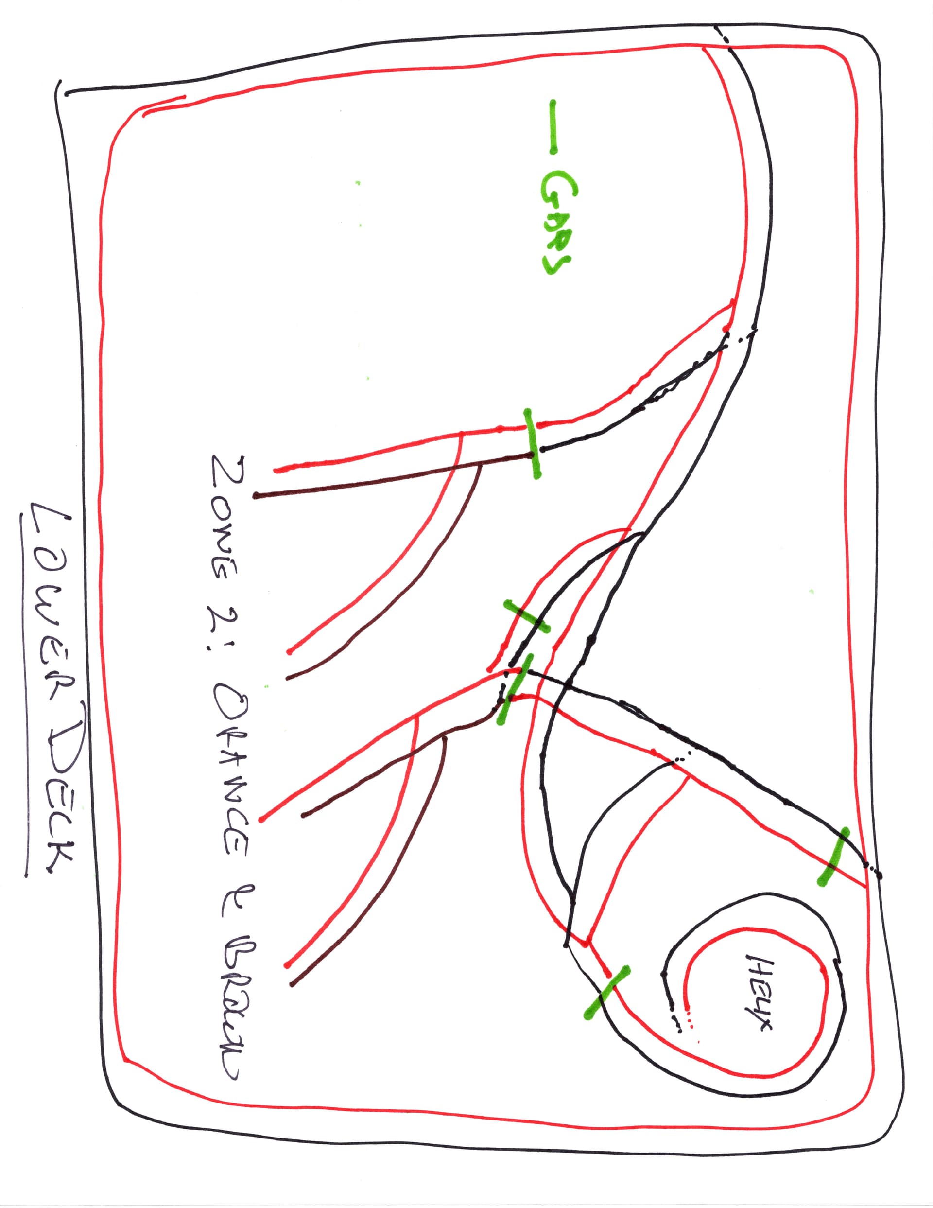
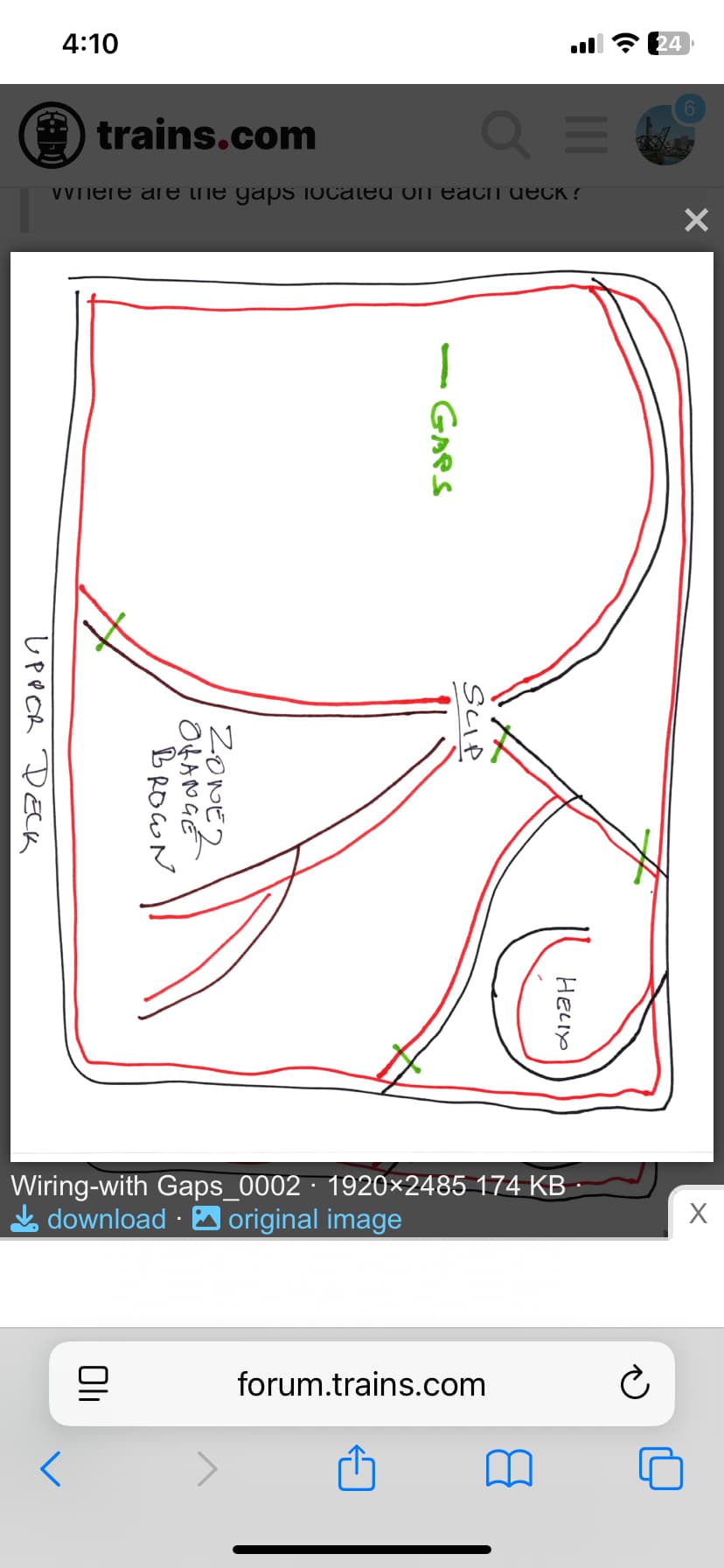
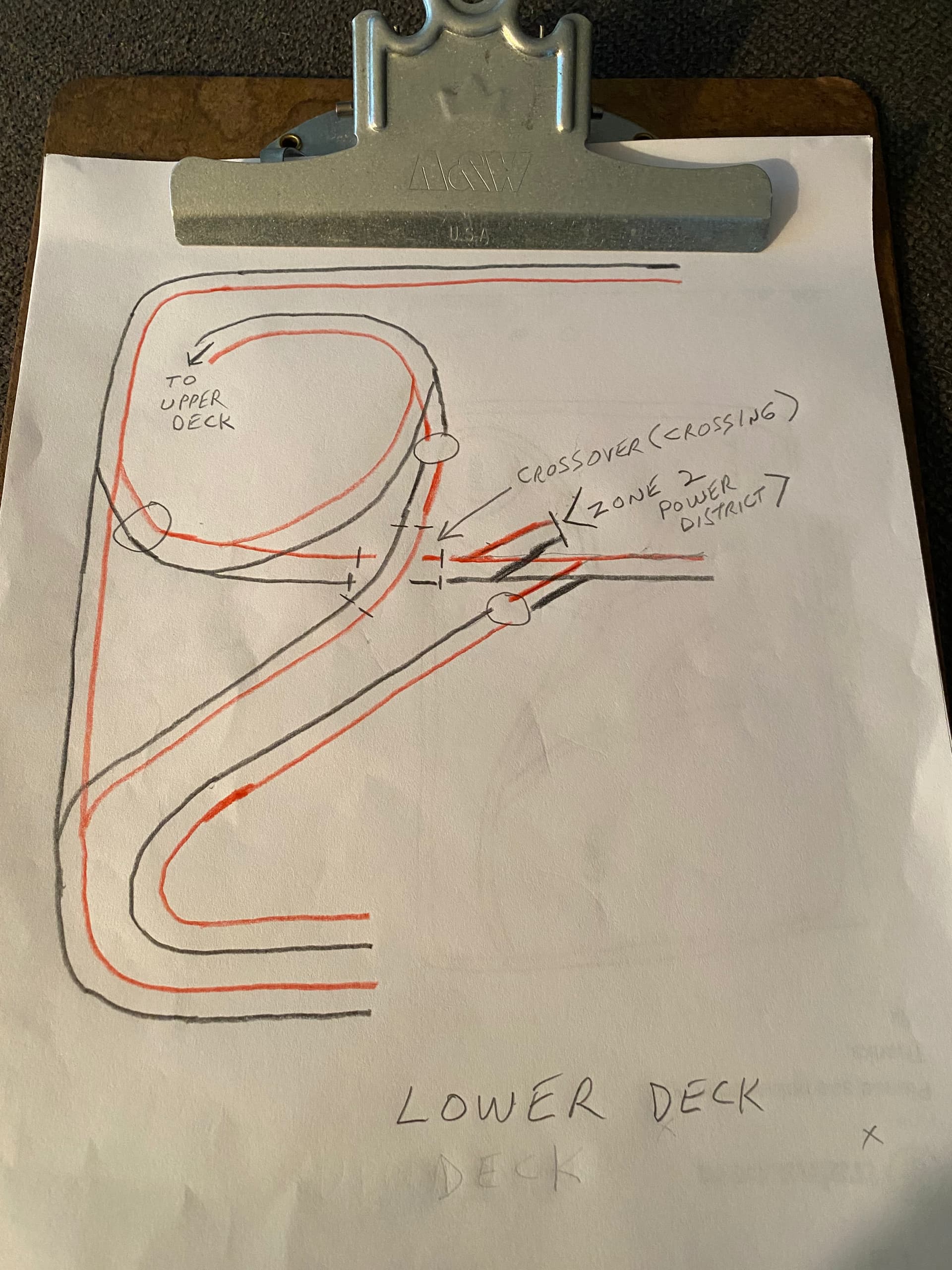
Need to see where your gaps are on lower deck
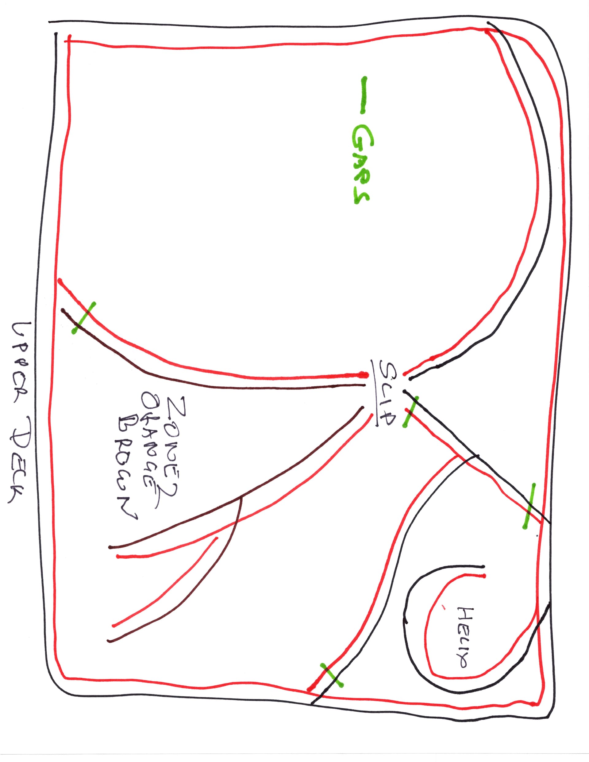
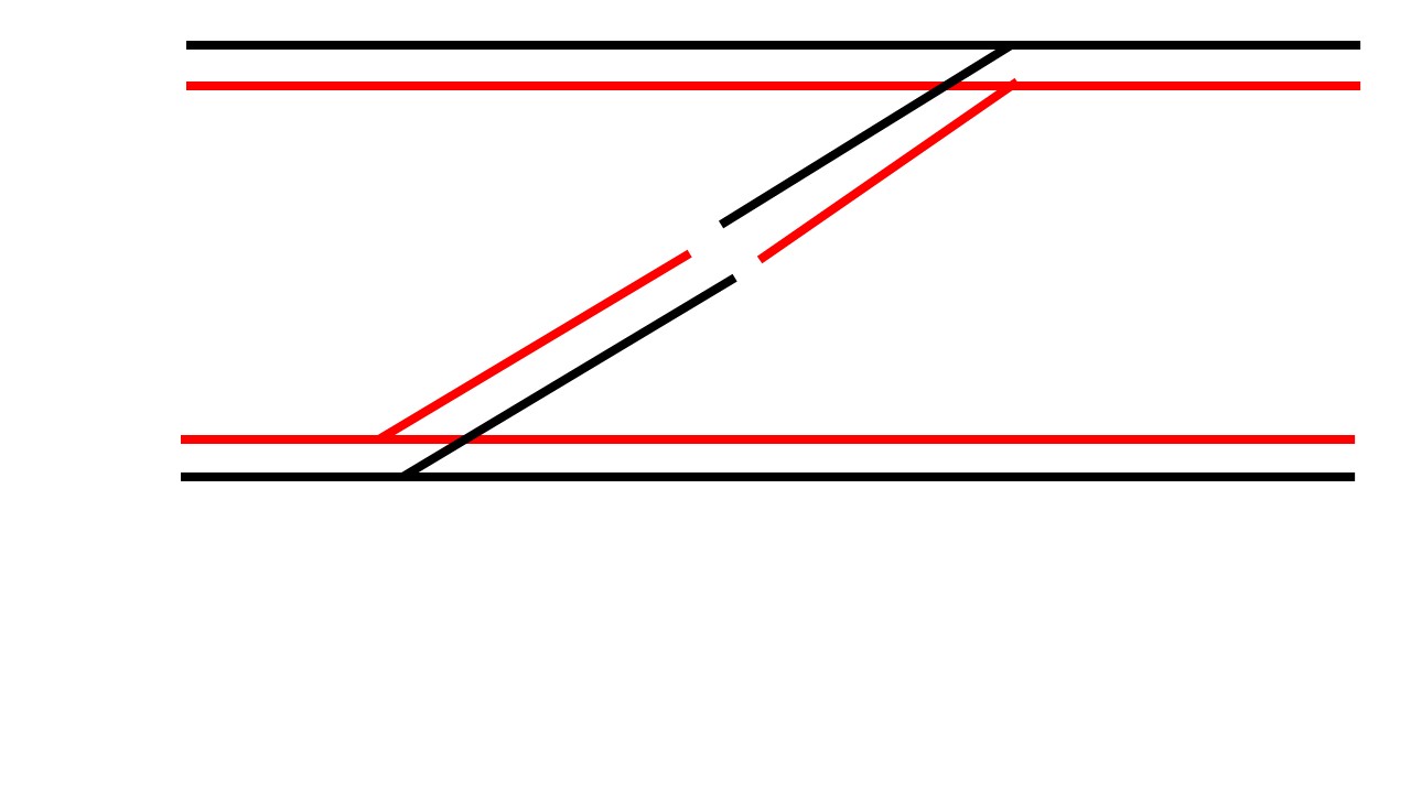
On the Upper Deck, the connection from below the helix to the rails to center is not done correctly on your diagram. Black does not connect to black, and red does not connect to red. It should look like this, a polarity mismatch.
The slip, presumably a double slip, in your Upper Deck diagram is highly contorted but it appears to be wired as shown in the top drawing in the following diagram. The correct wiring is shown in the bottom drawing in the following diagram.
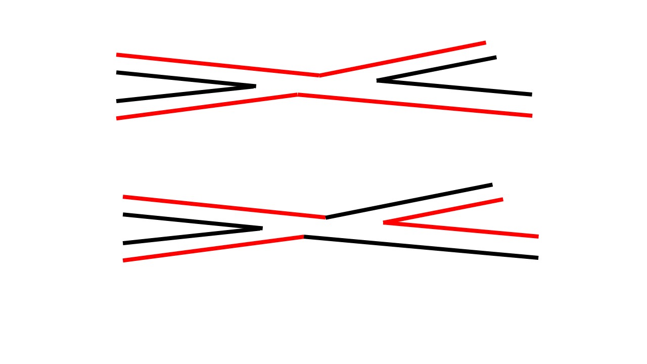
The bottom drawing corresponds to your most recent wiring protocol, but it still presents a shorting problem on the divergent routes.
Rich, you should edit that bottom drawing to explicitly show the gaps.
1 Like
It’s an excellent point, but I decided not to do that at this point until the OP takes a look at the problem. I am working on a solution that eliminates the need to gap the slip. That slip, located where it is, really, unnecessarily, complicates the Upper Deck wiring and gapping.
Rich
Hi Rick and Woke_Hoagland,
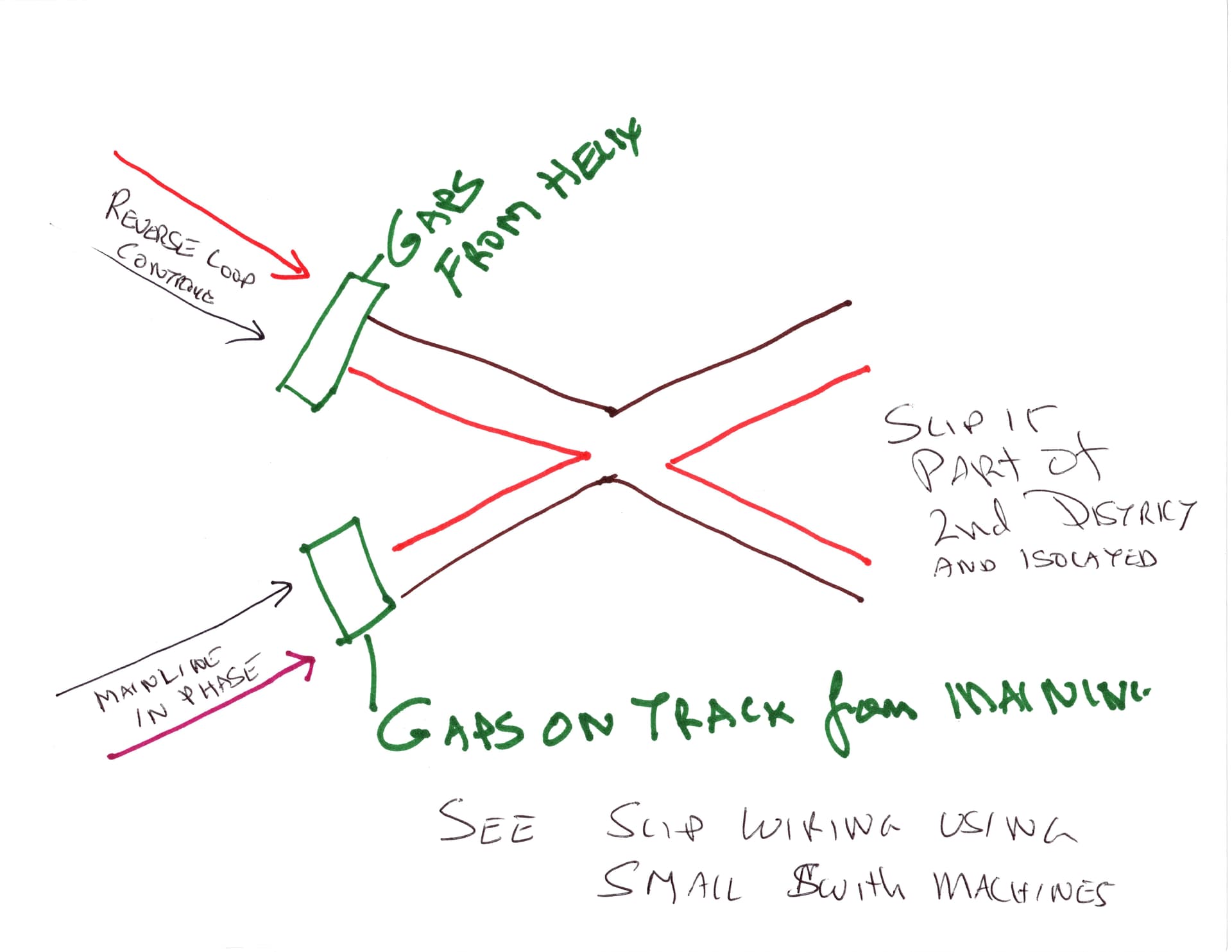
Let me try to clear slip issue.
- slip is entirely in a separate power district.
- It has both rail gaps on track coming from lower part off mainline as well as t reverse loop that comes from the upper mainline and helix Please se my drawing I am uploading
- Double slip itself is wired as recommended in: https://dccwiki.com/Crossovers_and_Slips
using SMAIL switch machine Frog Switching
Please let me knwo if I am missing something here
Thanks
Vik
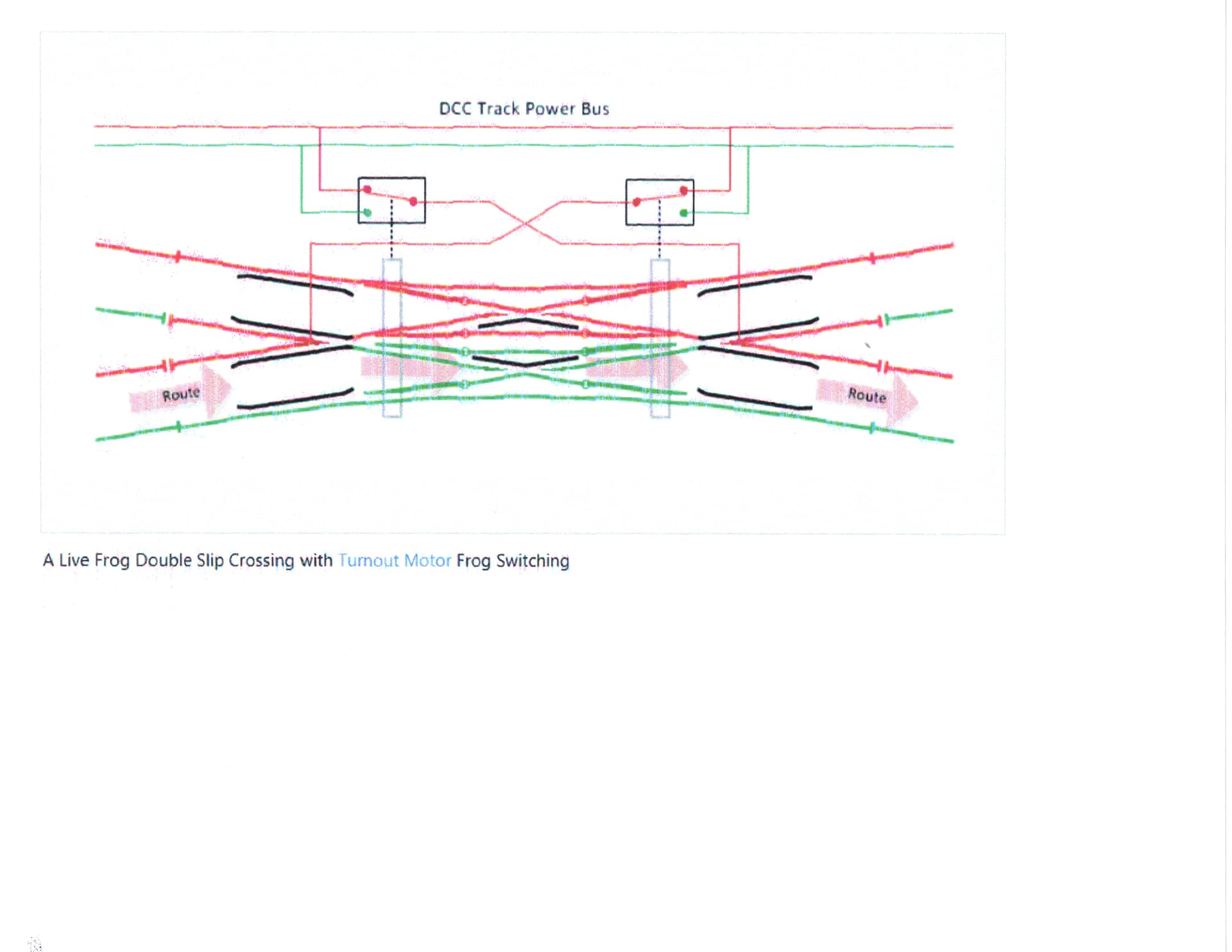
The2nd upload is from the DCC page
Well, unfortunately, that’s not what you show in your latest drawing.
The slip is not shown in a separate power district.
That’s what really burns me up about this thread. It is ever-changing, and way too much time is spent trying to resolve wiring and gapping issues when there is no certainty about how the layout is actually wired and gapped. This has been a total waste of time.
Following a diagram in dccwiki may or may not be helpful depending upon whether a modeler’s situation matches that of the example used in dccwiki. Does yours? Who knows.
I apologize for being a scatterbrain.
But i did try to talk about a separate power district
again I do apologize
Regards
My point, Vik, was that on Sunday, you posted a diagram of the Upper Deck, showing the wiring and gaps, and the slip was not shown as part of a separate power district, and the slip was shown as only partially gapped. So, I proceeded to redraw my diagrams to reflect what you had drawn on Sunday. Then, today, you post a different diagram.
Here is the main problem. At this point, no one, except maybe a psychic, knows for sure how your layout is wired and gapped. In addition, the double slip adds an element of complexity because, depending upon the type of double slip, it may or may not be power routing, and it may or may not have a live frog. That makes a difference.
Maybe it is the fault of the guy who did shoddy work and then walked off with your money. Dunno. But if this were my layout, I would start over with the wiring and gaps. The one thing that appears to be constant is the track plan itself.
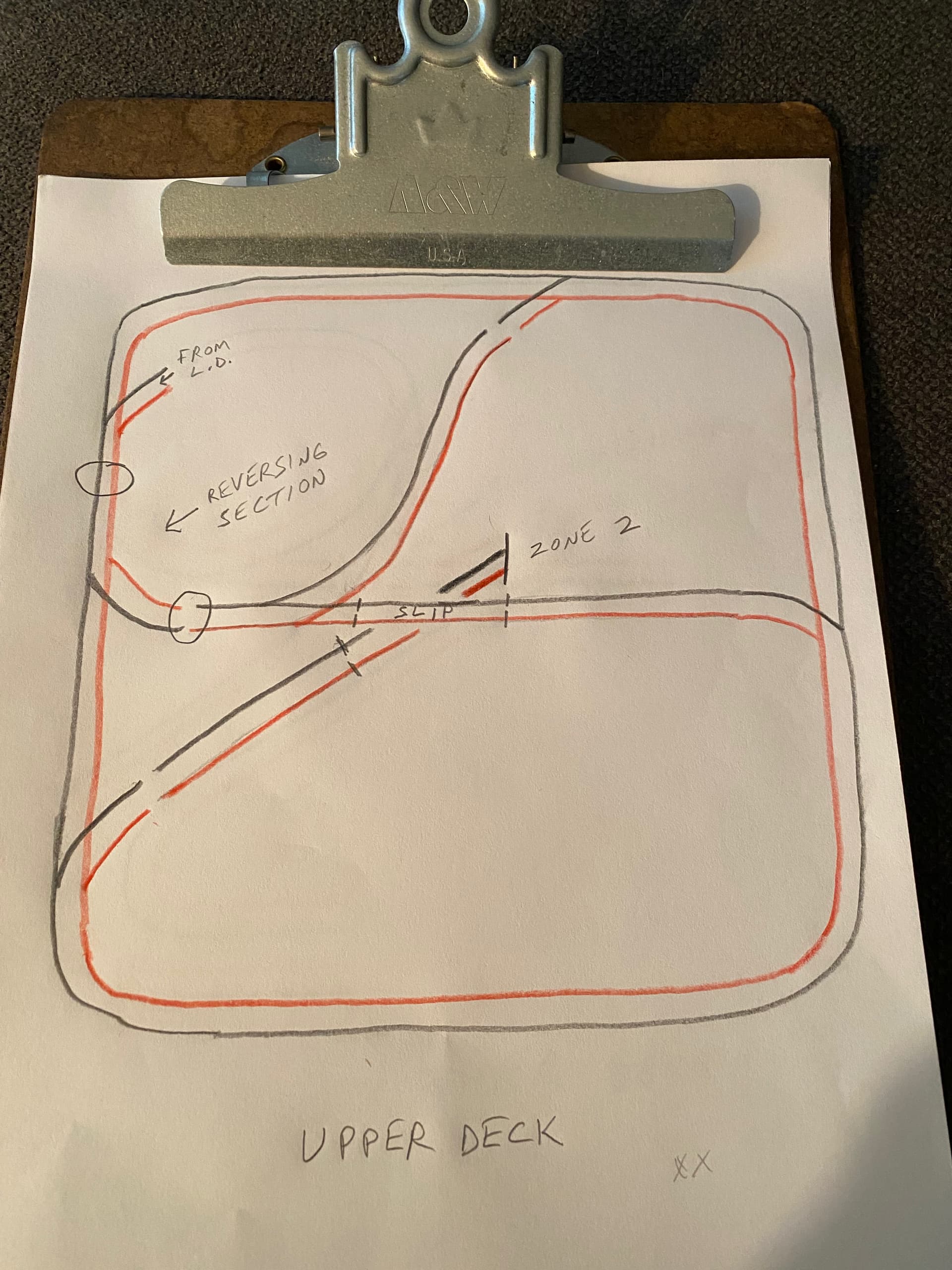
So, on that basis, here is how I would wire and gap the Upper Deck. Take note that I have significantly changed the wiring protocol (red over black / black over red) and created a smaller reversing section, isolated by two sets of gaps.
Rich,
Thank you
I really appreciate it.
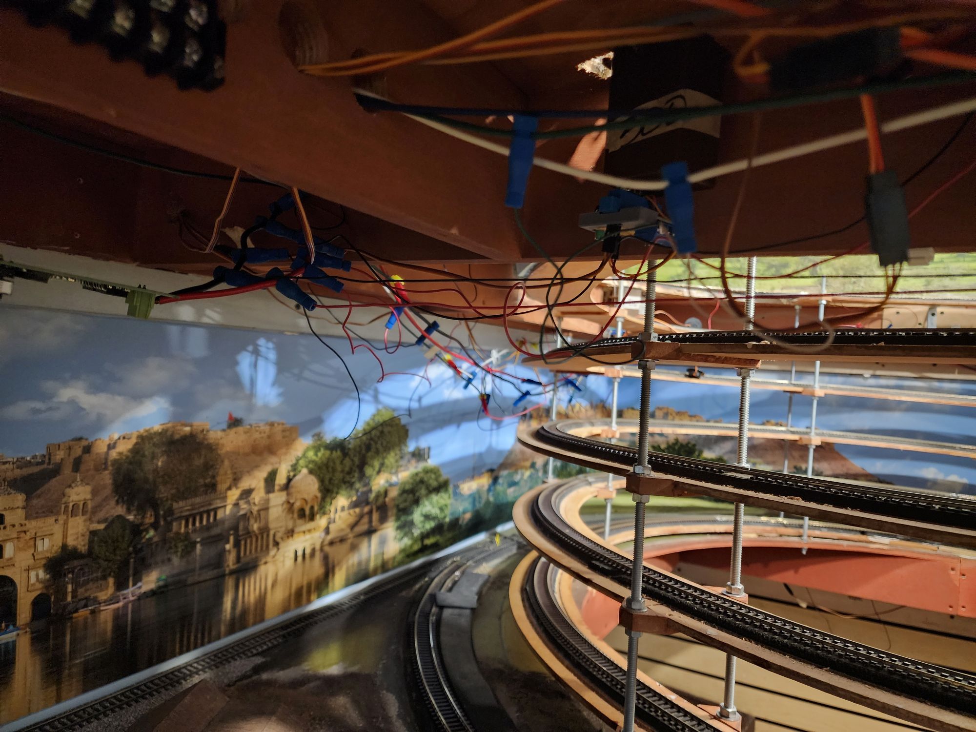
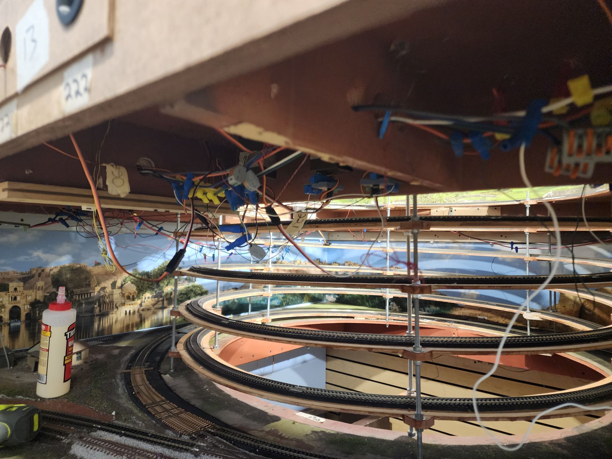
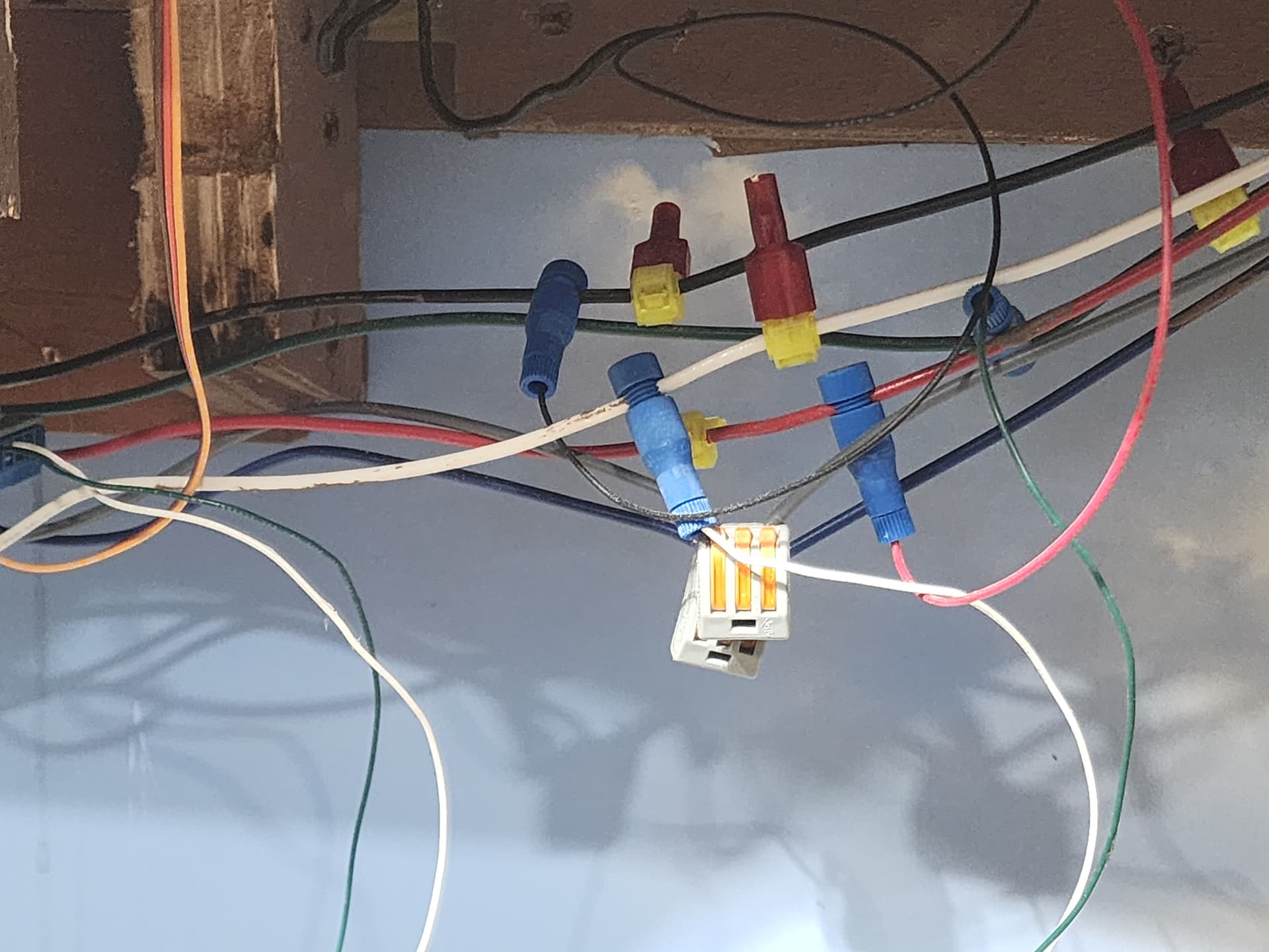
Not an excuse but this is what I have when James Adams from Affordable Model Railroad left and ran with my $$$
Not a pretty sight and I am slowly replacing all of it including some track and all. It is slow going and a complete cluster.
thank you very much.
Regards,
Vik
Vik, thanks for that follow-up reply and the photos.
I went back and looked at your website once again, and I spent some time watching some of your videos. The layout looks pretty nice, and the track work seems pretty decent. Exactly how operable is your layout at this time? In other words, can you navigate most of the Lower and Upper Decks without problems? Can you pinpoint the specific spots where problems occur?
I also took a look at the website for AffordableModelRailroads.com. The Railroad Designer, James Adams, seems to have a legitimate business and part of its Mission Statement says:" We will not close the project until we have completely fulfilled the terms of our contract." So, I am curious why he decided to stop work on your layout before it was completed.
It is hard to tell from your photos the condition of the wiring. However, from all that you and I have been through on this thread, the wiring protocol and gapping of the rails will be critical to the successful operation of your 2-level layout,
Aside from the gaps that set off the “Zone 2” power district on each level, it seems to me that 3 sets of gaps are required on the Lower Deck, and 2 sets of gaps are required on the Upper Deck. Each deck appears to have one reversing section, so one auto-reverser would be needed on each deck. Early on, you indicated that you are using PSX-AR units to perform the auto-reversing. These are excellent units, and I use them on my layout.
I believe that the latest two diagrams that I posted on this thread are what are needed in terms of wiring protocol and gapping. I am hopeful that you will be able to replicate these designs with your gapping and feeder wires. From the two photos you posted, it is hard to tell the quality of the wiring. How many pairs of feeders are there throughout the layout. I don’t expect an exact count, but do the feeders appear to be every 3 feet, 6 feet, etc.? I just wonder how much work you are faced with.
What type/brand DCC system are you using?
At this point, I don’t know how you plan to proceed? What is your plan? Would you be able to take overhead photos of some parts of your layout if requested?
Rich
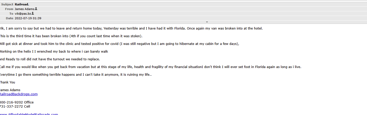
Rich,As to James from Affordable model railroad walking away here is a small sample from his email to me: "
Here are some pics regarding the state of affairs:
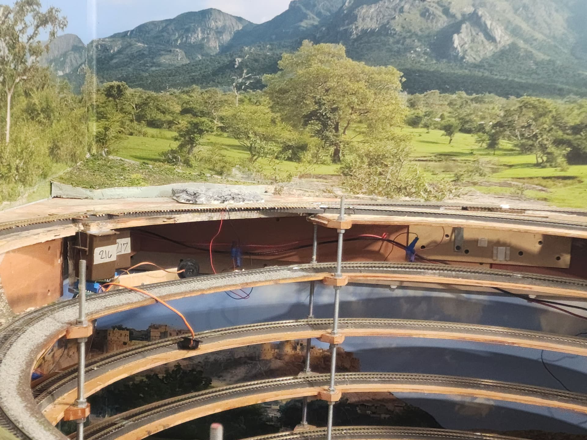
I have never been able to run a train throughout any deck completely only partially as derailments and shorts occur constantly.
Most of teh videos on my site are from teh old layout which Affordable/James also build. We moved homes in 2018 and I gave him a contract for this one, after full discussion of what i wanted and approval of a track plan. He delivered the lower deck in late 2018 connected it to DCC and there were obvious issues as to derailments and shorts.
Unfortunately Covid put a stop to it till 2021. In 2021 he made many trip to build the upper deck and finish up, but he issue never went away.
Big issues were curved turnouts (Pic attached sample)
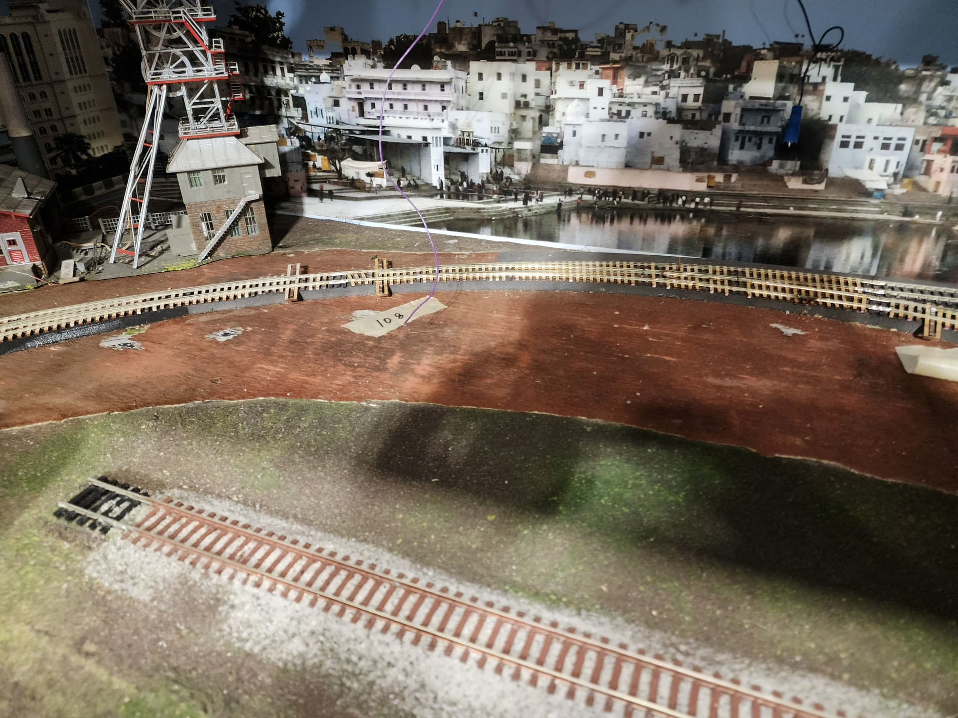
He decided to replace with fast track turnouts but most of them have closure rail issues as they were not soldered correctly.
Anyway he by this time had build teh scenery but had to take it out as a lot of teh turnouts were having issues .
I want to continue to get it to a fully operational state. May take time. At the moment I am looking on the lower deck once i can run thru it I will start on upper deck.
My DCC systemn is an ECOS system
Yes I should be able to give you pics if you want.
Thanks for the help.
Regards,
Vik.
From what I read in that email, none of the issues encountered were your fault. It sure doesn’t seem that he fulfilled the terms of the contract. Have you demanded your money back?
Rich
Regarding the status and condition of your layout, you have my sympathy. It’s not only the wiring and gapping that’s at fault. As you point out, there are track work issues as well.
Best of luck to you in trying to repair your layout.
Rich
Yes I have, but no response. My only option is to sue him in Civil court and all that it entails
which is an issue. Some people just have no honor or commitment