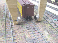
Homemade magnetic uncoupler

I’ve done a little experimentation with some Radio Shack ceramic magnets I have, using them hand-held a la the Rix thing and have gotten it to work in a fashion. I am thinking that perhaps if I were to mount them in some sort of holder, I’d have something that will work pretty good. Since these magnets have hole in the center, it shouldn’t be too difficult to cobble up something that allows for some adjustment of the spacing of the magnets to achieve optimal performance.

I’ll be going out of town for the weekend, so this project will get put of hold for a few days, but I’ll be back and let you all know how it turns out.

Thanks for all the ideas.

I’ve used 1" ceramic permanent magnets throughout my layout with fairly good success. I buy mine from Radio Shack. They come 5 to a pak. You need to use two magnets side by side. I just cut out a 1" section of cork bed and place the magnets directly against the bottom of the railroad ties. push a couple of coupled cars over the magnets and slide the magnets until you get a good response. Once you have them centered properly you can ballast the track and you never know they are there. I then use roadside structures or bushes, piles of coal or dirt to Identify their location when operating. The only problem I have with them is they are a little too short so you have to be fairly precise when you uncouple the cars.

Diamond Jim,

Actually, the rather short field length of the magnets as you describe your installation may be an advantage. That minimizes the chances for accidental uncoupling, although it does require rather more exact spotting to uncouple.

In fact, IIRC the orientation of the Kadee uncoupler is parallel to the rails, while with the paired small round magnets the field is perpendicular to the track. This is a good insight into how things work, presuming my physics isn’t flaky here.[*-)]

The Kadee uncoupling magnets are not magnetized over the length, but over the much shorter width. The 2 long edges are your N and S poles.

The couplers work by drawing the trip pins outwards, towards the 2 rails. So the magnetic lines of force have to be more or less perpendicular to the track (offsetting from true perpendicular about 5 degrees works even better).

If using the rare earth cylinder magnet pairs, they are installed with one N pole up, and the other one S pole up to generate the transverse lines of force.

The higher the magnet(s) is/are, the more horizontal the magnetic lines of force. Obviously, the practical limit is slightly below rail height to avoid physical interference. Conversely, burying the magnets lower creates more of a vertical component to the magnetic field, which has a more adverse impact on steel axles. If the lines of force at axle height were truly horizontal and transverse to the track, steel axles would not be an issue.

Fred W

Fred,

OK, that was definitely a low confidence level guess on my part[:$]

I’m better with the hands on approach, so got some neodymium magnets today. They’re 0.5" (12.7 mm) diameter.

Using my fingers, I experimented enough to figure out you want these magnets to be oriented with the same poles toward the other. The interaction with this field caused the coupler “hoses” repel each other. OK, this is good.

Took some measurements, a minute at the bandsaw with some 1/4" ply, and a hot glue gun. Here are some pics

You can see the magnets need to just clear the car sides, handrails, etc. You also need to get the magnets lined up as closely as possible on the two arms or prongs. I didn’t get this quite right, level across, and it seems a little touchy, but works fine. This shot is with the two cars sitting on the siding. Before they’re pulled apart, it looks like nothing is happened. However…

There is forced being applied and when you pull the car away from the other, voila! they oppose each other and spring open. The coupler on the left/top corner needs a little lube and hangs up a little, but it opens enough to allow uncoupling.

Here’s a better shot showing the clearances around the coupler. Mine is for HOn3, although I’m sure to make standard gauge ones, too.

The fourth and last image shows what happen when you don’t keep things centered. It drags the car sideways off the track! The

Mike

Wow! I was talking totally past you, and I apologize. I was thinking of under the track magnets, not a portable uncoupler like you have pictured. I have to admit I am surprised you found the like pole orientation worked well. I am guessing (without knowing) that the size of your magnets, and their being in a near horizontal line with the trip pins allows them to work well. By setting the magnets up to repel, you decrease the strength of the magnetic field between the 2 magnets.

My tests buried 1/8" diameter by 3/8" long rare earth magnets vertically either just inside or outside the rails. I use just inside for standard gauge, and just outside for HOn3, although this does not seem to be critical. The top of the magnet is set flush with the top of the ties. As far as I can determine, the coupler trip pins are simple iron wires with no residual magnetism in them (steel wire like used in paper clips holds a residual magnetism with a definite polarization). The Kadee trip pins are simply attracted to the strongest magnetic source (usually the closest end of a magnet). By having one of my magnets with N pole on top and the other with S pole, they reinforce each other’s magnetic field (like putting 2 batteries in series). So I use very small magnets.

Fred W

Fred,

No problem. I’m still mystified on this end about this stuff to a certain extent. Physics wasn’t my strong suit, so I ended up writing about it sometimes – on a good day. [:)]

Getting things down in print that effectively describe what’s going on can often be a challenge, one I know all too well.

I don’t think the round form factor is best for this application, but that’s what I have available. I suspect the field may be strong enough that I can do with just one per side, once the beta version is out.[8-|] Doubling up was as much a factor of cutting things just a little wider than needed as it was planned or needed with the prototype. I tend to eyeball things, then guesstimate the measurements to cut, then be as accurate as possible on the final version. Shop’s too cold tonight to cut another stick, but hope to do one tomorrow.

Since I want to narrow it anyway to fit in among close-spaced yard tracks, if one magnet per side still has the strength needed to operate, all the better. I’ll be able to make six uncouplers, instead of three, for $9 worth of magnets.

I cut another fork that was narrower between the tines. I also placed the magnets lower. When I estimated things last night, I went with the coupler centerline in placing the magnets. However, what I want to attract, the metal “hose” area, is lower. So I lowered the magnets for they were flush with the bottom of the tines, also hoping to improve operation.

Equipped with single magnets on each side, ver 1.0 just wasn’t strong enough for reliable operation. So I doubled up the magnets. That worked pretty good, except the limited amount of steel in the cars was enough to cause problems letting go of the car! Hmmm, not good.

So there must be a happy medium. Returning to my slightly wider prototype fork, I also lowered the magnets so their lowest part matched the end of the fork. This solved the slight misalignment problem. Single magnets still didn’t have enough omph, so I went back to double magnets. After this mod, ver 1.1 did work better than it did in original configuration.

For the record, for HOn3 the inside tine width on the successful prototype/ver 1.1 is 1.75", with the magnets sitting inside of that of course. Two magnets stacked together is 7/32" for reference, leaving a gap of about 1 5/16". The less successful narrowed fork ver 1.0 had a tine width was 1.5", so you can see that this measurement is critical to achieving satisfactory performance; slight changes will cause big differences in whether it works well or not. Not all magnets are the same, so this optimal gap will vary.

Obviously, for different scales and, perhaps, even gauges you’ll have to determine optimal inside tine width for the magnets you use with them, too. I tried them on standard gauge cars and both are too narrow and thus have too strong a field to work right, tending to derail the cars. I will probably try a tine measurement in between the two to see how that works for HOn3 and a wider tine for standard gauge, so will post those when I do.

BTW, I haven’t tried these in actual operation so f

I used a magnet that I found at Ace Hardware. They come 2 in a package and they are about 1/2" x 1/2" x 2". I put them directly under the ties with the strongest side up. Ballast over them and you don’t even know they’re there except for the track-side “markers.” Works for me and they’re cheap.

Dan

Well, I finally got around to cobbling up something. Its pretty crude but it sort of works, which I take as progress for me. I think I am going to have to fiddle around a bit with spacing and the like, but at least I think I am barking up the right tree. Or at least in the right forest.[:)]

Thanks, Dan… I’ll try that one!

Bob

In Great American Layouts dvd series, Gail Freitag shows how he made electro-magnetic uncoupers for his Stony Creek & Western. If your after electromagnets, this looks like agood design. Good luck!