Thank you for replying I understand about not seeing what i have done i was seeing is this thread was still good first off and them what information would be needed Thank you again Ted
Thank you Bob I ordered all those parts from them off a list you have put up found some the had the 100k resistor replaced with a 220k and thought that may be the problem At first my try’s did not work until i remembered i had one of those new light bulbs over the work bench Stupid me haha them i had one that the led glowed and would get brighter is i held the emitter up to it real close but am going back over everything tonight Thank you again Ted
Ted:
Glad you are sorting out the problem.
Dave
One of my current projects is installing grade crossing flashers. I find the between-the-rails phototransistors work pretty well even in very reduced ambient light, but if I dim the room enough they will stop working. So, I’m playing with IR LEDs. I have a few hooked up and they seemed to be completely useless, but I put a meter on the phototransistor and found that the IR LEDs are extremely directional, and if I don’t point them pretty much directly at the phototransistor it won’t get enough IR light. So, now I need to take some more careful measurements and determine the “cone” sizes for both the LED and the phototransitor, and make sure I mount both of them accordingly.
Very interesting comments Ted. Since you ordered parts from my new list, try building both Circuit 1 and 2. Could you give us a report on how you did in about 1 week?
Circuit 2 is 940NM IR light bouncing off the bottom of the car. Notice that the IR Photo transistor has a heat shrink cover? About a 1/16” dia. hole is in the front. This is like you are in a well looking for the moon. When it is over head, you see it. Say +/- 15 degrees off center you don’t. Now 10u Amp of reflected IR light will produce 1 Volt DC at the 100K, then the Darlington will give 10 m Amp of current to the Red LED. (Your Lamp, incandescent bulbs and day light all have 940NM IR light, then the Red LED may never turn off.)
Circuit 1 is the lost of light. The IR Photo transistor does not need a heat shrink cover! The shadow of the car over the light sensor turns off ANY light source, and the Darlington stops shorting out the LED.
Bob Frey
Robert Thank you Yes i will be trying again on both circuits 1 and 2 I will report back later this week Had to take a break from this project Still very interested in making this work
up date on my attempts : Built circuit 2. works and lights the led when in room and off when shadowed Built circuit 1. led on all the time and gets brighter when in room light or with IR emitter Going to try this one again tonight Tried to post pictures but do not understand how Happy so far got circuit 2 to work. Will just have to change indicator led to green to show clear track. For now Ted
Ted
I think the trick to circuit 1 is to try to prevent any direct room light from getting to the receiver. That’s where the heat shrink tubing is crucial. If the receiver can ‘see’ any of the room lighting fixtures then it will trigger the sensor. I use a 1/16" drill shank to control the size of the opening in the heat shrink tubing. Put the tubing over the LED, then put the drill shank into the top of the tube so that it rests on the top of the LED, then apply the heat. You want to form a ‘tube’ with a 1/16" inside diameter about 1/8" long above the receiver. That gives a very narrow ‘viewing angle’ so the receiver can only ‘see’ what is directly above it. When a car passes over there is plenty of IR light to bounce off the bottom of the car and into the receiver, but the narrow angle will hopefully cut out direct light from the ceiling fixtures. Placement of the ceiling fixtures is obviously an issue. If they can shine directly down the tube then they will trigger the sensor. Please remember that I described the sensor as being “basic”, as in “very”.
Dave
Hello Thank you David for the reply I do not have the shrinkwrap install but did buy it as per parts list Good tip on the drill bit use ! My circuit 2 is not working with room lights (i changed the bulb in my workbench light) it needs a bulb almost touching it All my room lights are fluorescent (was my first problem) I have bought all the parts to change over to a track light system and hope to use dimmable leds. Is there a way to adjust the sensitivity ? Are the IR collectors used black in color? Making sure I was sent the right ones Ted
Ted:
Sorry I didn’t get back to you sooner. IR receivers are often black so the ones they sent you should be ok.
If you don’t have the shrink tube installed then the circuit will suffer from too much extranious light and will not work properly.
Without adding in more components to allow you to adjust the sensitivity, the only variable is the shrink tubing. You could do a series of tests by starting with a longer piece of tubing over the receiver and then gradually shortening it a bit at a time to see what changes occur.
Something that I did to test the detectors was to set up a short piece of track on some 2" pink foam insulation, including cork roadbed. That allowed me to mount the detectors in a controlled environment to see how they worked. I did have trouble initially with light coming from my workbench but when I turned off the center light that was shining directly into the receiver tube things worked ok. There are two other lights over the workbench, and all three are within three feet of each other. The center one is halogen and the other two are CFLs.
Dave
Bob Frey’s IR Cover Box Circuit
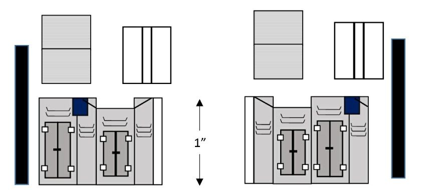
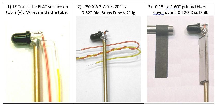
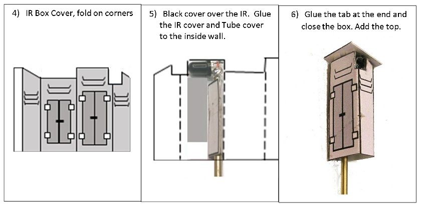
In this IR Cover Box project the 3MM IR DARK (940NM) photo Transistor is covered with a 0.15” black wide shield to form a 0.120” dia. viewing area. In the past a shrink tube with a 0.062” dia. viewing area was used. By putting two IR (940NM) in series, this increases the amount of light that can be detected to 3 feet. This IR Cover Box can be printed on card stock, or a 3 x 5 picture with 1”= 1” when printed. Link: http://1drv.ms/1CuZ9a4
Part No. &nbs
File: IR_Box_Circuit.pdf Link: http://1drv.ms/1CuZh9s
Bob Frey’s IR Cover Box Circuit. Was anyone able to print this Link?
A simple IR beam to over 3 feet.
http://cs.trains.com/mrr/f/744/t/246394.aspx
Bob Frey
Hey Bob
I printed that out no problem
I’m still working on you simple circuit
Can’t get it to work with the lights farther away then 8 inches
But it works
Ted


