Thanks David, that is the approach I plan to use. I think I “get it”. I am using a bus line for my track DCC power so I have a little experience with that concept. What I am not clear on is how to use a wall wart as a power source ie how do you connect the 2 bus wires to the fairly short wires from the wall wart. Do you then have to plug/unplug the wall wart to control the lights? Thanks again to all for a really great collection of tips on this!
Either locate the power adapter, (wall wart) in a handy location or splice wire onto the packs wire to extend it where you need it. Run one wire from the pack around the layout as the common or negative/ground wire and connect one lead from each lamp to that wire. Run the live or positive wire from the pack to one side of an SPST switch or switches to control the lights. If you are using one switch to control all then run your live buss from the other side of the switch around the layout. If you are using more than one switch you may have to run wires to individual bulbs or have more than one live buss for your lighting. In either case, connect the other lead from the lamp to the live wire and that should do it.
My power supply that I use to run my lights is from an old 486 AT computer that I bought new back in '95. Although it’s puts out much more power than a wall wart it is essentially the same in that it’s a transformer. I have it connected through a dusk to dawn light fixture so that it functions only when the bright room lights are off. The other lights in the room aren’t bright enough to make it turn off. The light fixture in turn is connected to a switched outlet on the side of the layout so I may turn it off when I don’t want it to go on when the room lights are turned off.
This works well on some buildings. These are cheap bulbs and sockets I got from IHC. I think they were about 50 cents for the bulb and socket, with pigtail wires included. The flat-based socket can be glued to the layout base, so you can lift the structure off and leave the lighting and wires in place. If the bulb burns out, it can be simply unscrewed and replaced. (I took this picture before I punched the hole through the base and mounted the socket permanently.)
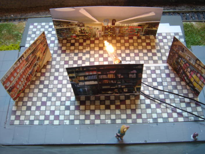
It’s important the bulb not be visible through the windows. That produces a bright point light source which is really annoying. Here, I shielded the bulb with a piece of cardstock. I printed up pictures of store shelves on cardstock and used that to make an interior for the building. This makes a difference if the building is right in the front of the layout, like this one, or if it has big windows. The floor, once again, is printed on cardstock. The cardstock interior can also be glued to the walls to further block glow-through, particularly in structures made of thin plastic.
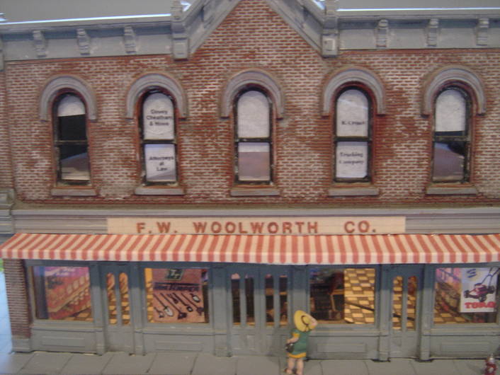
The second-floor window shades are made of tissue paper. I didn’t light the second floor, so I put a piece of styrene between floors. The window shades make it hard to see into the second floor, so you don’t notice that there’s nothing in there. The window signs upstairs (Dewey, Cheatham and Howe, plus the R Crumb Trucking Company) are home-made decals applied to the windows.
If you get lucky, you can find a connector that matches your wall wart DC connector. Radio Shack maybe. Or cannibalize the connector out of what ever the wall wart used to power. If the connector can be obtained, I would use it; when doing maintanance, it’s always nice to be able to take things apart without having to solder them back together.
Coming back to real life, you may not be able to get a connector to match the wall wart. In that case, you can snip off the wall wart’s connector and splice the wall wart wire to your under table lighting bus. Or you can use a barrier terminal strip. Wrap the wall wart wire and the lighting bus wire around the same screw head. Polarity doesn’t matter, just so long as the lights are incandescent lamps, not LED’s. LED’s do care about polarity which is one good reason not to use them.
One good way to splice wires is strip the insulation, twist them together and then solder the joint. Then insulate it with heat shrink tubing, or plain old plastic electrical tape. Or, use wire nuts. Or use crimp on inline splices which a good hardware store will have.
If you want to switch the lights on and off, simpliest is just plug and un plug the wall wart. If you want a switch, consider plugging the wall wart into one of those switched power strips the computer stores sell. Or, plug the wall wart into an ordinary extension cord, and then install one of thise in-line switches such as are used to switch table lamps.
I know this may sound very primitive but I have had great success with Chistmas lights! One string has about 150 and my layout has plywood base with foam board cover. I mark were the building will be then drill small hole to fit the bulb thru. Tape the bottom so it won’t slip out and that’s it. I do use individual lights hooked up to to a bus line powered by an old train set poer sully that works great for the main street lights.
Thanks again. So many great ideas! Think I am ready to give it a shot, once the market rebounds and I can afford a wall wart!!! Mr. Beasley your photo card interiors are an outstanding idea!
That looks terrific, Mr. B.
If I used an old computer power supply (and I have plenty of them), what would be the best way to add a dimmer in the circuit?
I tried putting a dimmer inline between the wall socket and a computer power supply once. You don’t want to go there. You can put it on a dusk to dawn switch but a dimmer just doesn’t work, at least it didn’t when I tried it.
Thanks. I wondered about that. Seems like there would be a cheap dimmer to put on the 12 volt side of the power supply available somewhere, but I really don’t know what to look for. I guess I should ask in the Electronics Forum.
Rather than adding a dimmer I think you would have to make the power supply a variable supply.
Something like this maybe?
http://www.wikihow.com/Add-Variable-Voltage-to-Your-ATX-Based-Bench-Power-Supply
Thanks Kevin. That looks like something simple enough that I might be able to build it. Just out of curiosity, what would happen if I wired an ordinary household dimmer between the 12v computer power supply output and the string of 2.5 volt Christmas tree bulbs I’m planning to use in my structures? Would that work?
BTW, I think I know how to wire the bulbs (about 50 of them) in a combination of parallel and series such that each bulb gets no more than about 1.5 volts. I’ve tested them with an old MRC power pack and they seem to work fine.
I can’t say I have tried that but just off the top of my head I would say it won’t work well at all and might harm the supply. What is generally done with low voltage household lighting is to install a dimmer on the line, (120V) side before the transformer. You could try that I suppose by wiring a dimmer to the outlet the supply is plugged into. Just be careful not to illuminate yourself! If you are not experienced working with line voltage don’t do it. I don’t want to read about you in the papers. [;)]
Thanks. I never touch anything that’s 120 volts. Scares me. But I have an inline dimmer (if that’s the correct term) around here somewhere that has a regular 120v wall type plug on one end and a regular plug in socket on the other. I bought it years ago at Lowes and never used it for anything. If I can find it, it seems like the risk to me should be low. If I blow out the transformer, so be it. I’ve got several more that are just taking up space.
I’ve tried that before and all it did was blow the fuse in the power supply. Something in the electronics doesn’t like partial power. Those dimmers are designed for use with lamps and such, not electronics.
Lots of good advice here. I’ve been into electronics for work and play for over 50 years, and still made notes of many of the suggestions. For my 2-cents worth: Decide on a lighting voltage and lamp mounting before starting and stick to it as much as possible. I decided early to light most of the structures on my layout. I found a good deal on some 6V bulbs with leads to start. Later I found a special on 12V bulbs with sockets. Then fell in love with LED lighting. Saw a special on 16V bulbs with adhesive base and leads. etc, etc. I now have 7 different power requirements, 10 if you count animation power, and only a few of them work because of the complexity of wiring and powering such a mess. Still having fun, though!
As was mentioned, running incandescent lamps at reduced voltage increases their life. The life varies as the inverse twelfth power of the applied voltage! I run 12 volt lamps at 9 volts and can expect a 32-fold increase in life. I expect I never will have to replace a lamp.
John
Most transformers have accessory terminals. The esiest way I think is to run your wires from each terminal, (there will be two), under your platform to structure areas. Having purchased lights from a hobby shop, one wire goes to each of the wires from the accessories. Kind of like diagram below. The vertical lines represent the wires from the bulbs. I cut a small hole through the platform where the structure would sit and dropped the bulb wires through to connect to the access. wires. I cut insullation away to connect bulb wires without having to tie wires at each accessory. See second diagram. Each vertical line reps. another accessory.
-----I--------From access. 2nd diagram. --------l-------l-------l—
-----I--------From access. --------l-------l-------l—
I also try to use a seperate transformer so the lights aren’t affected by train operation causing dimming of lights. A cheap one will do the job. Hope this helps.
cooltech[8D]
What a great idea!!
cooltech[8D]