Thank you for the really quick response. I have cleaned the contacts on the relay, carefully rechecked the wiring and even replaced the battery. I did not open the horn to clean the contacts there since the horn does work perfectly when the relay contacts are closed. I also checked for continuity through the coil.
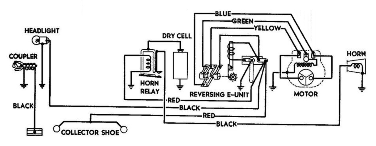
See here for the schematic for your locomotive. Put the loco in neutral and power it up, checking for AC track voltage on the horn relay coil wire and ground. Switch your meter to DC volts and press the horn button on the transformer. Check for about 1.5 volts DC on the coil contacts.
The relay coils rarely fail, usually the problem is wiring, or the movable contact does not move freely.
Thanks, Larry. Several of the grandkids are here for the weekend so I probably won’t be able to check until they go home tomorrow. I’ll be back in touch.
Ron, there are a couple ways to replace the sliding shoes. One is to have a Rivet press set and those are quite expensive with all the tools. The other is to buy some roll pin punch sets you can use with a hammer to flare the rivet. You can buy the shoes and rivets from WWW.ttender.com, Jeff Kane. It may be a bit of a learning curve to get them right. You will need a vise or something rigged up to support the rivet head from the bottom. Roger
Larry and Sir James, got the chance to take a look at the locomotive this AM. When getting ready to perform the test Larry outlined, I rechecked wiring and connections and with embarassment have to report I found a faulty connection with the relay ground wire. It was corrected and the horn functions as intended, with its usual crummy sound.
It is good to hear that you found the problem and have your horn working.
One other quick test to insure the horn is getting full battery voltage. Check the horn directly with a fresh battery by putting the bottom of the battery on the metal of the horn itself and touching a wire from the top of the battery to the horn wire on the relay. If it sounds better than the horn being sounded normally, then the battery circuit needs cleaning.
Bob. I just got 2344p NY central-mint condition Engine. I am using the 275 watt ZW transformer. My Whistler units for my tender coal work fine. This particular locomotive with regards to the Whistler does not work. I heard it go on for less than a second and then I couldn’t get it back using this transformer. Should I buy a separate switch for it or can you shed some light on what I could do?
Take off the shell. Put the locomotive on the track, with the voltage up and the direction in idle. Watch the whistle-relay armature as you try to blow the horn from the transformer. The relay is immediately forward from the D-cell. The armature is a metal flap on the bottom of the relay. There is a contact on the armature that moves up and down and a stationary one on the relay body. Let us know whether the armature moves, and we’ll go from there.
Returning to the comment about a 2023 locomotive and it’s ability to pull a train, I find that on a layout of a modest size, 6 x 11, where I have a 5% grade, the locomotive and dummy and three passenger cars in the anniversary set are a real challenge. My solution has been to run two powered units back to back. I have disconnected the E unit in one of the two powered locomotive and run wires through the port hole in the doors of the Locos so that one unit controls both motors. In that Way, both move in harmony. I think the several years ago, Bob Nelson commented that all you have to do is lock one of the E units in neutral position, but I never was completely sure how to implement that, although it sounds simpler than what I did.
You do have to run wires to connect the motors together, but you don’t need to disconnect anything–the slave unit’s e-unit does that for you when you put it into neutral.
You can get away with only three wires, two for the brushes and one for the fields, but I thing it’s a good idea to include two more, for the pickups and the chassis.
Another trick is to run the wires over the tops of the couplers and lashed to them with ty-raps. This keeps them neatly together, especially on curves.
Bob—Not sure I understand neutral regarding eunit. Here’s what I think that I understand. The Eunit is a swithch built on a solenoid which changes position every time the current comes on And energizes the solenoid. in this way current flow through the motor changes every the power is starts But if the e unit lever is moved to the other position, the current doesn’t pass through the eunit solenoid and routing of electricity thru the motor stays as it had been and the motors resume their last movement. If by neutral, you mean this last eunit off position, I don’t understand how that guarantees the other e unit controls both motors.
Pls explain
yr comment re the wires on the couplers is excellent and I’ll try it
I’m calling the successive positions of the e-unit: forward, neutral, backward, neutral, forward, etc. In each of forward and backward, the e-unit drum and fingers connect the armature in series with the field winding. But in neutral, the armature is completely disconnected from the rest of the motor, so it’s as if all three wires had been unsoldered from the motor. That leaves the motor free to be connected to anything else that you want, without actually removing any wires.
All you have to do is to sequence the slave locomotive’s e-unit into neutral, then shut off the slave locomotive’s e-unit, then wire the master and slave motors together. From that point on the master and slave motors will be controlled by the master locomotive’s e-unit. It is possible that the two motors will want to run in opposite directions. If so, just swap the two new wires that you put on the brush holders.
The wiring can be as permanent or temporary as you like.
the whistle on my 2023 works when manually tested. With voltage up and direction in idle, when whistle is in on position there is a buzzing noise, the light gets brighter but the armature doesn’t move.
This is my first train, I got it from a friend who was the original owner. When I got the train there was a black wire connected at only one end. There was an old solder spot at the top of the solenoid so I connected the broken wire there because I couldn’t find a wiring schematic. The wire now goes from the center connection on top of the solenoid to the outside connection point.
Thank you for the wiring diagram. May I assume that grounding is accomplished by contact with the locomotive base/frame? If that is correct, I think my wiring is intact/good.
Should the front set of wheels remain magnetic when the locomotive has been off the track for a period of time? I also expected electromagnetism in the relay for the horn when the whistle control is activated, there was no magnetic force on the armature.
There are stiff wires by the coupler on the front of the locomotive. One side is soldered, the other is not connected and resides in the square by the coupler. Could this be interfering with the ground.