That’s an interesting approach, and I for one would like to see detail pictures and perhaps a diagram of the detail construction.
The idea of using the brass toolbox latches as electrical contacts is ingenious. Keeping the contact good between the saddle and locking bail ought to be relatively straightforward, although if the latch came lacquered from the factory a little judicious removal and cleaning at the various contact points would be advisable.
I presume that the actual alignment is made with adjustable plates and that some sort of pin-and-socket arrangement near track level is used for fine alignment of track ends. I further presume that if only one latch is used per side that the ‘other’ contact is made through contacts or pins up near the track – what arrangement was decided upon? Only one pin or plate per end would serve for electrical return…
Well, I’ve learned quite a bit from this discussion and I want to thank everyone for the ideas. So we all end up on the same page, let me clarify a couple of things. The section is hinged on one side with door hinges and drops down to provide access to the door. When lifted it is locked in in position with two slide latches underneath. I have figured out how to flow power to the section with the hinges using simple track wireing. What I’m struggling with is how to transfer power across the section to the other side when lifted in place. I didn’t mention that two tracks enter on each side. In order to avoid running off the layout on that side I isolated about six inches of track on that side from the main layout with insulated rail joiners. I thought I would be able to use the powered lift up section to transfer to the isolated sections of track there by powering the small unpowered section. The reason I titled this post “microswitchs” was I thought that when two opposing switches came in contact and were connected by that action the power could be transferred.
Whew! Lots of good ideas and now I’m headed to the train room to evaluate what the best solution is.
I’m surprised the slide latches give good enough railhead alignment – they may start to sag over time. Same with the slip in the hinges over time. Hence the various advice about V-channel lateral alignment, adjustable plates, engaging pins etc. to get both ends precisely located when closed.
Probably the ‘best’ way to get power is to treat the approach, the door, and the opposite side track sections as being fed by drops from the same feeder… and wire them all as drops from a common feeder, routing wire around the benchwork, through a channel on the floor, using flexible wire as indicated above to power the door, etc.
Note that you can happily run feeders across the underside of the bridge in 14 gauge and design the contacts at the end of the bridge to have corresponding area, connecting to more 14ga feeder on the other side. Then just wire up to the individual rail or track segments, which will then be only a few millivolts at most different from each other. This may involve a couple of amps at 14-15V, but that’s not really a contact hazard, and then you can use a micro switch of appropriate rating to interrupt the hot feeder going to the door as a safety cutoff for the approach, the door, and the section beyond the door.
You don’t need contacts at both ends of the bridge to power the bridge rails.
You don’t need the bridge to power the approach tracks either.
What you’re looking for is a switch to cut power to both approach tracks at the same time I.e. when the bridge track is dropped.
Power the bridge and have the bridge then power the approach track to the hinged side using the joint between the bridge and the approach track to switch off the approach track when the bridge opens. The bridge track can stay powered.
Power the open side approach track, as an isolated section, from the “other side” of the layout with an interrupt to one rail wired to the gap. Only one wire on each approach track needs an on/off switch, so only the one contact switch is needed and that at the open end.
I’ve been trying to make a way to go under the fold down section and connect when it’s up by using some type of connective like RCAs. Now I realize I can go over and around the exit door frame. It’ll be a lengthy piece of wire, but I’ll figure it out…
This way I have plenty of circuits for turnout (Tortoise) supply, lighting DC, signals, main track buss, plus the section of track directly connected to the bridge.
Plus, a Cinch-Jones can only be oriented one way so circuit integrity is good and they will handle something ± 10 A.
I use one pair “looped back” so that when the plug is disconnected a series circuit opens. This opens a relay that A, kills the track for about six feet either side of the “chasm” and also drops the signals to red.
My drop bridge is twenty-six years old and I haven’t detected any sag, wear, displacement or even thermal shifting. I used a commercial steel hinge that has ball bearings and adjustable thrust washers. We DID have an mb 5.0 earthquake near here but that was in '86 just before I began the layout.
The opposite end, however I use two dowel pins plus locking
I had some help from the GE machine shop, too [:-^]
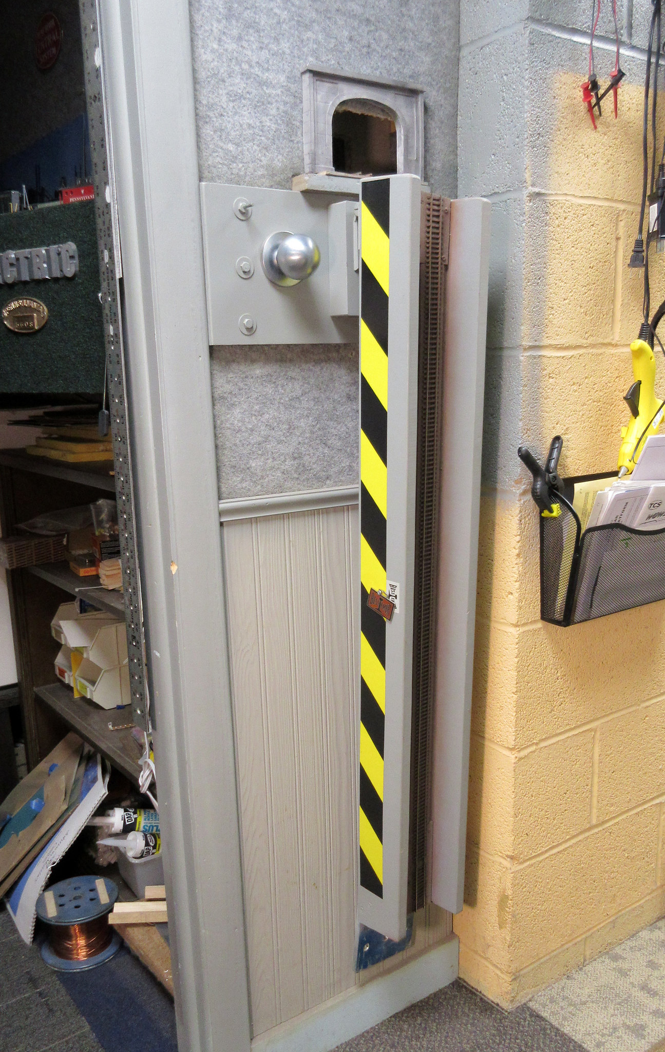
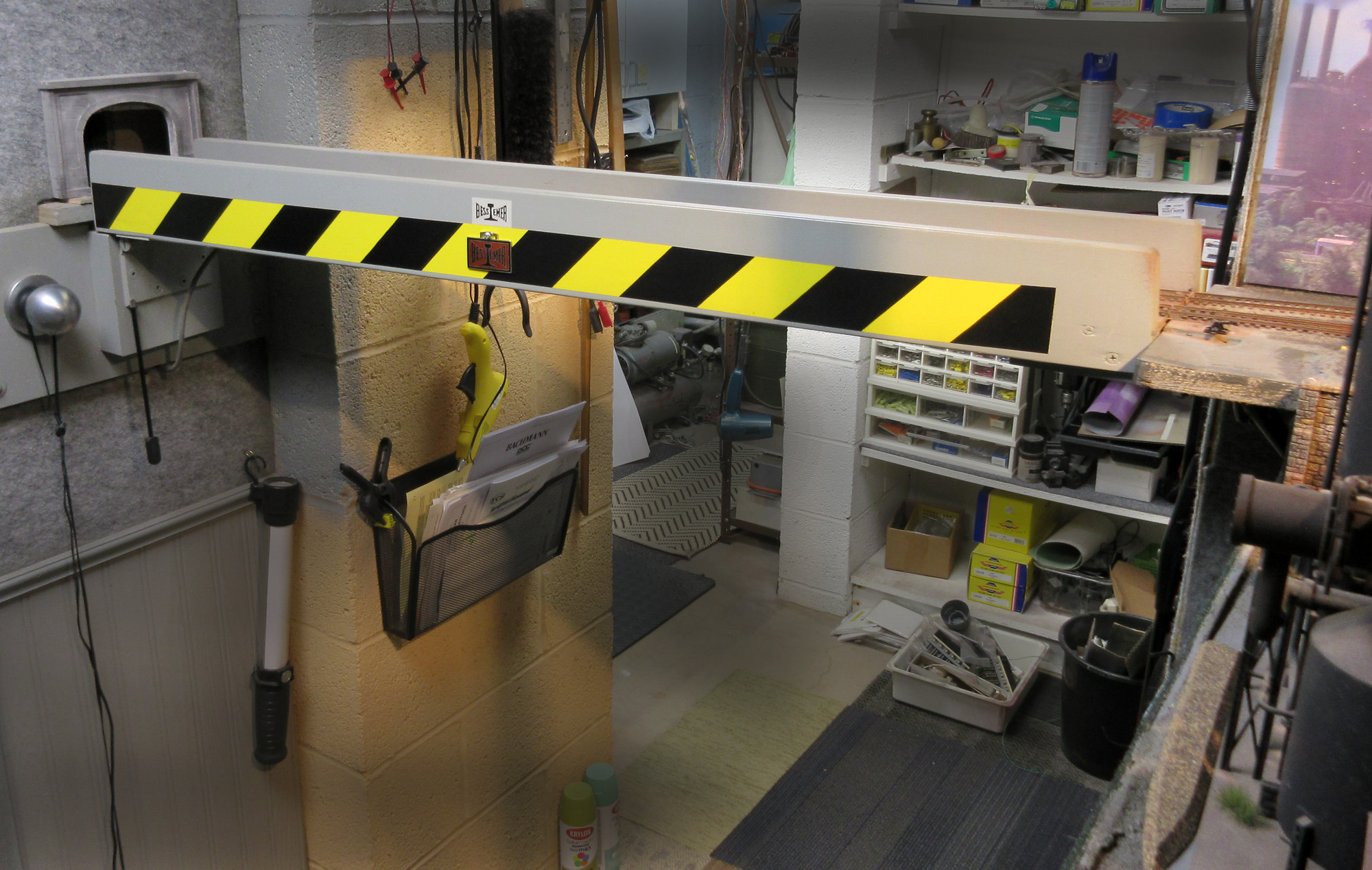
This bridge spans the doorway into my workshop and has masonry walls on either side of it although there is 2 x 4 wood framing over that. Still, there has been very little adjustment ever needed and I’m pleased with the operation.
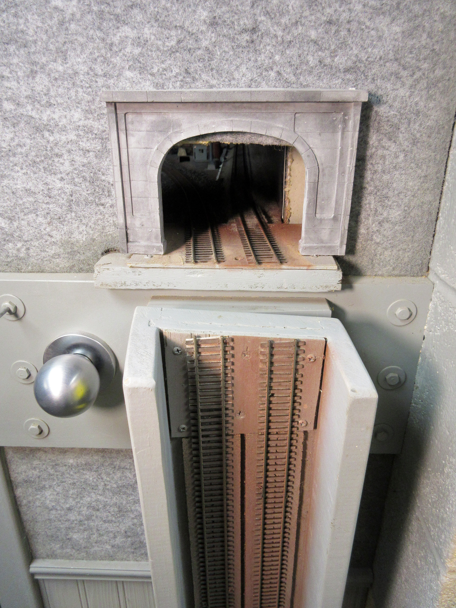
It was just luck that the bridge, when down, fits into its own little out-of-the-way niche and isn’t prone to bumping. The bridge itself is made of furniture-grade maple with the track base dadoed into the side rails.
I recommend a drop-type bridge whenever practical over a lift-up type. Seems to make more sense to me, anyway.
Unless, of course the FORCE be with you and you can have one of those superheterodyne virtual styles I read about in M-R some time back [:D]
How do the vertical side pieces clear the underside of the track as you lift the bridge into the locked position?
What’s the door handle used for?
Am I seeing an angle in the joint at the hinged end? Is that a design requirement to make this work or just the way your track runs across the gap at a slight angle?
The ends of the side “girders” are slightly beveled and clear the mating stationary side very well.
A: It’s a conversation piece. Many visitors ask “What’s the door handle used for?”. B: I’m an old man. I grab it sometimes because when I don’t lower the “gate” I still use it as a duck-under. C: It is a handy place to hang things, such as test leads, extension cords, Opti-Visors, etc. that I am either using on the layout and need to return to the shop or vice-versa. D: I installed door hardware for “paired” steel doors and this was left over from the job and I hated to see it go to waste.
There’s a definite offset of the right-of-way here. About 10°. The hinge is bolted to a solid block of aluminum [:|] and was milled to the 10° angle. The resulting geometry is perfect.
Thanks for the additional details. Those were questions that arose from the photos. It seemed to me someone, maybe even me, might want to build something similar and your answers provide important details not obvious from the photos.
One common thread running through the various bridge ideas is the need to design and build a robust bridge and attachment points (rather like the prototype in fact). You want rigidity, repeatability of track alignment and reliability in your bridge device to allow full enjoyment of the layout. Running valuable models over a space above a concrete floor requires confidence in your design and construction.
The thread is running long, but I need to add one more thing. On a section regardless of up/down or whatever, if both sides of the point where the tracks meet are powered right to the edge, how do you bridge the inevitable gap that will interrupt any DCC locomotive that is not equipped with a keep alive?
DC power is available from either side’s rail… and your wiring prowess has ensured, hint, hint, that the available voltage does not change by more than a few millivolts.
Even if you had only one wheel doing pickup, it will likely drop slightly into the gap and therefore never go out of contact with a powered rail segment.
The DC power in DCC is always at ‘supply’ voltage, and the DCC signal imposed on the power is equally and immediately available, in or ridiculously near ‘phase’, on both sides, so there won’t be meaningful control-integrity interference either.
This is no different from track with a poor-conducting track joint in which there are proper feeders to the adjacent lengths of rail.
This bridge spans the doorway into my workshop and has masonry walls on either side of it although there is 2 x 4 wood framing over that. Still, there has been very little adjustment ever needed and I’m pleased with the operation.
It was just luck that the bridge, when down, fits into its own little out-of-the-way niche and isn’t prone to bumping. The bridge itself is made of furniture-grade maple with the track base dadoed into the side rails.
I recommend a drop-type bridge whenever practical over a lift-up type. Seems to make more sense to me, anyway.