Yes I see the markings. I received my two HO transformers today. One does not have any DC output. The other has 18 Volt DC output, but it is all or nothing. It is either 18 Volt or nothing. There is no variation of the voltage from the control handle. This doesn’t sound normal. Is this OK?
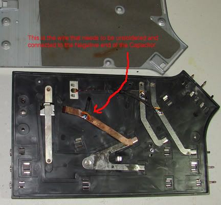
Below is a picture of the inside of my turnout. As I understand you I connect a new wire (22 gauge OK?) to the two wires from the coil that I will unsolder. The new wire is routed outside and connected to the Negative end of the Capicator. Once this is done I should be able to put the turnout back together, correct?
No, those are the wrong wires. Notice that they are connected to the control rails, which are the short outside rails that make the non-derailing feature work. Leave them where they are. Instead, unsolder the other two wires that are both connected to the center rail. Then connect both of those two wires to the wire that will come out of the turnout. Yes, 22 AWG is fine for that.
Be sure to insulate the new connection adequately, and route the wire where it will not get pinched or cut when you put the turnout back together.
I just now went back and looked at the picture of the supplies that you bought. They are Tyco 899Bs. I couldn’t find any description of the circuit; but I’ll bet they are 18-volt supplies with a rheostat in series with the output. That’s the traditional HO way of doing things. Measuring the voltage with a voltmeter, you wouldn’t see any variation, because of the high impedance of the voltmeter. If that’s the case, you can use the one that works with no problem; just turn it all the way up. The full 18 volts will probably be fine for powering the capacitive-discharge part. I think that the 18-volt output is a clue that they are intended for slot cars, not trains.
You will need a 12-volt supply to power the LED assemblies that you bought. If you can find a similar supply meant for HO trains, it should have a 12-volt output, which would work with your LEDs. Making your own LED circuits, designed to run on the 18 volts or whatever AC or DC supply you want to use is also still an option, instead of getting another HO supply.
OK, I edited the picture in my last post. It only looks like one wire, but are there two wires? I’ll look for another power source. Will I be able to use just one HO Train transformer for all my LED indictor lights?
I haven’t drilled the frog yet, but that wil be no problem. I just need to get to the hardware store to get a new drill bit of the correct size. Thanks.
I have used a 7/64 inch drill for 6-32 x 3/8 inch flathead Phillips screws. I recommend drilling from the bottom, all the way through the frog, then threading the entire hole.
Thanks again, another good tip. I have been away all weekend, but tomorrow I will pick up a new drill bit and the 6-32 screws. I already have the taps. I used to do a lot of machine work, so this shouldn’t be too hard. Do you know what the frog is made of? Is it brass (unlikely) steel or a pot metal?
The frog is die cast zinc. It is soft but it will weld to the drill bit. WD-40 works well for cutting oil. If you cut it dry the bit may weld to the frog and break off. Don’t ask how I know these things. Bruce Baker
Oil is a good idea. I’ve never had a bit break in one; but the tap gets stopped easily. Do a lot of back-and-forth, back the tap out frequently and clean out the chips, and don’t try to advance more that about a quarter-turn without backing up a few turns.
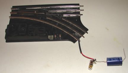
The frog is drilled and tapped. The Negative end of the capacitor is soldered to a lamp socket and to the new wire from inside and the new wire is routed out the bottom of the turnout base. There was a nice slot so I didn’t have to drill a hole. Will the lamp always be on, or will it only be on when the capacitor is charging? I used a lamp socket so I can change the bulb easily when it burns out.
When you say the Positive side of the capicator is attached to an outside rail does that mean I can connect it to any outside rail or to a buss wire under the table that connects to the outside rails?
I should have my new 12V transformer in a couple of days. Then I will be ready to connect the toggle switch to the turnout and to the indicator lights.
Any of the above; that is, connect the positive side of the capacitor to any outside rail other than the two control rails or to any wire or transformer post that is connected to the outside rails.
Then you can go ahead and connect up the 18-volt supply that you already have, since that’s the one to use to charge the capacitor. Connect the positive side of the supply to the outside rails, or etc. Connect the negative side of the supply to the free terminal on the lamp. The lamp will light only when the capacitor is charging. Then put a truck on the track over one or the other of the control rails, to test the capacitive discharge operation.
Something is amiss. I conntected the Negative from the Capacitor to the new wire to the turnout coils. The Positive side of the Capacitor is connected to one side of the lamp and to the outside rail. (I used a track connector CTC)
The other side of the lamp is connected to the Negative side of the Transformer. The Positive on the Transformer is connected to the outside rail via the same CTC track connector. The transformer is not marked positive or negative, but when I put my meter to the terminals with the negative lead on #2 and the positive lead on #1 it get an 18 Volt reading. I am assuming that #1 is positive and #2 is Negative.
When I apply power, the lamp goes on. How long does it take to charge the capacitor? I thought it would be pretty quick. When I run an engine’s front trucks onto the control rails nothing happens. I have power on the track via a 1033 Lionel Transformer. The lamp for the turnout indicator lantern lights up. I do hear a very faint buzzing from the turnout coils.
Have I wired this correctly? Could it be that the turnout I selected is no good?
Thanks for your patience with me with this. I’d love to get this right so I can start on the toggle switch and latching relay part of this.
You have it wired wrong. Neither lamp terminal should connect to the outside rails. Only the + terminals of the capacitor and the 18-volt supply connect to the outside rails.
Capacitor: + to outside rails, - to new wire and one lamp terminal
18-volt supply: + to outside rails, - to other lamp terminal
I don’t know your meter; but you’re probably right that 1 is positive.
The lamp should fully charge the capacitor in 1 2/3 seconds.
Got it right this time. Works perfectly. It is amazing how the turnout snaps into place when the truck hits the control rails. The Capacitor charges up just like it should. This is so much better than using track AC power. Can’t thank you enough.
I should have my new 12 volt transformer in a couple days, maybe tomorrow. I have a SPDT toggle switch. I assume of the three terminals on the switch two go to the turnout and the center one I’m not sure what goes to it. I have a latching relay. It is 12 volt DC. It is a SPDT, but I am confused (as usual) because it has six terminals on the bottom. There is a black band at one end. Does this indicate polarity? The pins on the bottom are numbered 1 3 6 on one side and 12 10 7 on the other. 1 and 12 are at the end with the black band. Does this tell you anything?
Congratulations! You’re right, the two outer terminals of the switch go to the two insulated turnout terminals. The center switch terminal goes to the outside rails generally. The switch does the same thing as the truck axles; it connects one or the other of the control rails to the outside rails generally.
Your relay has 3 terminals for the coils and 3 terminals for the contacts.
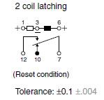
Below is a schematic of the latching relay. It is Greek to me can you tell me what gets connected to each of the pins? This is exactly how my relay is numbered. This came from the seller’s web site. I got my new 12 volt transformer today but I forgot it at work so will have to test it tomorrow.
You saved me the trouble of looking up the relay diagram–great! Pins 1, 3, and 6 are the operating coils, which will be connected in parallel with the turnout coils. Pin 3 is common to both coils, so it gets connected to the new wire that you installed, or to the negative terminal of the capacitor, which is the same thing. Notice that it requires a negative polarity, which is why we installed the capacitor and the 18-volt power supply the way we did. Pins 1 and 6 get connected to the same insulated terminals of the turnout to which you connected the SPDT switch. (You did try that out, right?)
We will use pins 7, 10, and 12 to connect the LEDs, one or the other, to the 12-volt supply. There are two equally good ways to do this; but here’s one: Connect the negative terminal of both LEDs to the negative terminal of the 12-volt supply. Connect relay pin 7 to the positive terminal of the 12-volt supply. Connect pin 10 to the positive terminal of one LED and pin 12 to the positive terminal of the other LED. If the colors don’t match the turnout position the way you want, swap the LEDs.
That is the least I could do. you have given me a lot of help on this project, and I am learning a lot about train wiring from it. Thanks. I checked out my new 12 volt transformer today and it seems to be ok. It has a set of constant 12 volt DC terminals on the side as well as a set for cab 1 and cab 2. It also has a set of AC terminals. I will probably use the constant DC terminals. The cab 1 & 2 rheostats don’t seem to work well. As soon as I start to turn the knobs they both go right to 12 volts and there isn’t much variation in voltage output. Is this normal with these old transformers? Every one I get seems to work this way. No matter, It will work well for what I need. When I get home tonight I will complete the wireing of my first turnout and see how it works. I’m building a little sample control panel so I can see how it all works. Can’t wait to see the turnout snap back and forth and watch the LEDs change from red to green. This is going to be so cool. Thanks again. I’ll let you know how it turns out.
Most of the early HO power packs use a rehostat(variable resistor) to control the output voltage. If you do not have a load(engine) connected to the power pack, the output will read 12V. Also, the DC is just rectified AC-- no filtering. For what you intend to use them for, they will work just fine.