I have used RTS for years, but this is a quick trial at my new expansion. However, I am never sure about getting the yard ladders looking right with when using RTS.
Here I am working on the yard that all the steamers and long frame locos will be able to navigate smoothly after picking up the train made up by the yard engines. So I will be using Atlas Custom Line #8s (as here) or at least #6s in this yard.
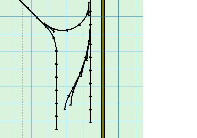
Am I getting this right? I will next used flex track off the #8 turnout to run 6 or 7 foot parallel yard lines down (with more switches-within-the-yard-thingys [my terminology sucks] for crossing over and by passing within the yard)
Does this look right so far? There is a south-running mainline to right and north-running to the left of proposed yard [ignore the loop at the top that is not connected yet…it is part of the 18 radii yard track for the yard engines to enter and return to other areas of industry]? Brown line is stud wall.
Just using RTS sectional track for planning because I am not so adept at manipulating the flex track in RTS. On the real layout, the sectional track will be flex track.
Yards are one of the places RTS does a poor job. You should be able to get your track closer together in real life. You certainly can with XtrkCAD or any of the paid programs.
It looks as if you’re creating a “pinwheel” ladder, where the throat goes through the diverging routes of all the turnouts, rather than through the straight legs after the first turnout. In your pinwheel, each straight leg leads to a yard track. In a conventional yard ladder, the first turnout begins the throat by going through the diverging route, but after that, the straight leg continues the throat while the diverging route leads into the yard track. In other words, the throat begins with a right-hand switch, say, but then after that the ladder is all left-hand switches.
Your approach has the benefit of making the ladder angle a bit steeper, which helps to deal with the compressed space available to us modelers. But each yard track has to bend back parallel to the main or primary yard track, and as SpaceMouse has mentioned this will result in a wider track spacing than might be desired. An option might be to place more turnouts just inside the ladder, to use up that space for additional tracks at a closer spacing. In other words, start the ladder with a RH switch, continue it with another RH switch, and then off of the straight leg of that second RH ladder switch, add a LH switch. Classification yards are often done this way, to get them to fan out broader - it’s basically like having sub-ladders off of each rung of the primary ladder.
I hope this makes sense! Try adding at least a few straight track sections beyond the switches, so you can see what your spacing looks like, whatever you end up doing.
Thanks WP&P, that is exactly the info I was looking for.
Thanks also Space Mouse. You know, RTS gave me absolute fits with the first yard I every planned…until I figured out it wasn’t me, it was the program. However, I am daunted by learning XtracCad.
On my first layout I used #4s and got the spacing closer only by physically trimming a good few inches (or as much as I could) off the top or bottom end of each straight leg of the turnout.
RTS will work just fine for designing yards. Just do not use the ‘Snap Switches’ ! Atlas Customline turnouts are designed to give you parallel 2" yard tracks. My layout was designed using RTS and everything ‘fits’ with no problem.
A ‘pinwheel’ or compound ladder can save space, but is frowned on by the real railroads. They are considered a safety hazard due to the switchmen having to cross live trackage to throw switches on the ladder.
Most anything(engine-wise) will negotiate a #6 turnout. The new Atlas #8’s are great for cross-overs; passengers cars will track much better and you will have less diaphragm hang up. Our club has #6 cross-overs and we really have had no problems with passenger trains.
Pinwheel and compound ladders are not the same thing.
Pinwheel ladders are a single ladder, but each successive turnout springs from the diverging side of the previous turnout. These are not especially common on the prototype, but are not a safety problem since the switchmen can stay outside the tracks (switchstands are simply moved to the diverging side.)
Compound ladders require switchmen to cross the tracks and so are rarely used on the prototype except in extremely tight quarters or in hump yards and similar situations where the powered switches are thrown remotely.
Diagrams of pinwheel and compound ladders (which show the clear difference between the two) are found on page 36 of the June 2010 Model Railroader magazine.