I can’t understand your sentence, but mine might have been unintelligible as well. I blame my sentence on my third 18-hour workday at the railroad in three days.
Note that the bridge you provided the photograph for is made up of many discrete spans. Long spans are rarely ballasted deck. These are not long spans.
Weathering steel remains in broad use today – very popular for railway bridges; we used it on several recent bridges. Cor-ten is a USS brand-name for weathering steel but other steel producers offer an essentially identical product.
I would recommend you unglue them and install them separately. Each rests on the pier on their own seat, which could be fixed or expansion. There can be a significant gap between them if the pier is broad enough.
The difference between what you are doing and what the prototype does is that you have created a continuous span. Railroads don’t often use continuous spans for something as banal as a plate girder bridge because the stresses are indeterminate, the construction costs skyrocket, and it provides absolutely no increase in value over individual spans. Think about how much harder it is to fabricate, transport, and lift in to place a 135-foot span vs. two 65’ spans.
Okay then, so what would go in the gap? It would be resting on the pier suspended in air, so how should it look like? What if the bridge was just two separate spans lifted in and welded together?
The two bridges might only have a gap of an inch, and the ballasted deck spans between. If open deck, the rail spans the gap.
Welding the bridges together (or riveting, or bolting – more likely!) would make the bridge a continuous span. This creates a negative moment over the pier, i.e., the forces are now upward not downward, when the bridge is loaded.
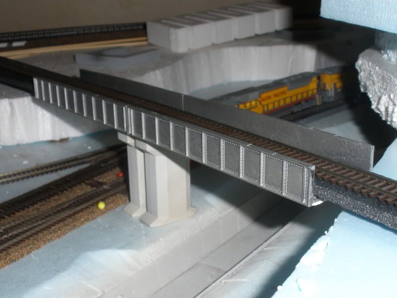
Useful to see the photo. There would only be one pier, not two. The piers are not quite right for this type of bridge – they are a highway type and of more recent design than the riveted plate girders of the bridge – sort of like a bridge from 1908 and a pier from 2008. They are a little small in section for the bridge. Worse, the chamfers on each side means that the pier is having to transfer the load from each of the girders into the center section of the pier, which requires a lot of reinforcing steel, a lot of extra cost, and delivers no value. Bridges built during this era used concrete that was only moderately reinforced (or often not reinforced at all), which makes this kind of a pier design troublesome, expensive, and of no intrinsic value.
A more prototypic pier for a railroad bridge would either be absolutely straight sided or slightly negatively beveled from bottom to top (smaller at the top), with the outside face of the pier outside the outside face of the girder. Any architectural ornamentation would be outside the vertical plane that projects from the outside face of the girder downward perpendicular to the ground because it adds no strength but could subtract strength.
I think as far as the one bridge vs. two in this case my eyes would never be good enough to see that you’d glued them together. A thin black line drawn at the joint would enhance the illusion.
Another point that I see about the Alhambra Valley bridge is that there is a fairly extensive area of public activity in the valley below. A ballasted deck will catch anything falling off passing trains such as brake shoes, or stray bolts, etc. when doing track maintenance. In more northern climates ice breaking loose from the running gear is a common occurence in winter. A few years ago CPR installed a protective barrier with walkway gratings on the underside of an HDPG bridge crossing a major expressway prior to a bridge tie replacement program. As well as catching any loose debris it made it safer and more convenient for the gang who would no longer need to always use their fall protection equipment.
And I will confirm Railwayman’s comments. A typical spacing between spans would be 3" if the fixed bearing for both is on the center pier. Except for very short spans, one end of each steel span will have an expansion bearing to accommodate the thermal expansion of steel, and minor shifts in the pier or abutment. When an expansion bearing is on the pier, the distance to the adjacent span will be increased.
Where the track pans are made of concrete, the ends of each span will have a steel plate to retain the ballast. A piece of sheet metal may cover the gap between spans, but is not universal. Sometimes the track pans will be of steel. On average the costs are fairly equal so it will depend a lot on the variations in price of materials by location or time, and of course any prejudices on the part of the engineer in charge. While I have had little exposure to timber ballast decks, they can probably be continuous since wood has a lot more flexibility than concrete or steel.
All decks will have some form of coating or waterproofing applied to protect the pan from the ballast and water. Steel can rust, concrete can be attacked by chemical reactions, and wood of course tends to rot when wet. But that won’t m
I have, but they do not have a plate girder bridge. They have a deck girder bridge, but it’s not only too short, but it doesn’t allow enough overhead clearance (below the bottom of the deck girder) for the tracks that the bridge is intended to cross over!
You are confusing deck versus through-girder bridges.
Haven’t you overlooked Micro Engineering’s 100’ single track through girder bridges? It is two 50’ bridges with support legs. The bridge is also offered in single 50’ sections so you can have bridges in multiples of 50’
Wow thanks! Yes, pretty much resembles what I’m doing (except for the columnal piers). Did you take the photos? If so, where is it and what railroad uses the bridge?