Thanks again GMPULLMAN, I will give this bi-color diagram a try.
JPD,
Make sure you double-check what type 3-legged bi-color LED you have/purchase. Most are common cathode (-) type but some do come with a common anode (+). That will make a difference how the LED is wired.
I needed a red-white LED to correct the classification/marker light colors on an Atlas H16-44. The locomotive came with red-green markers and the NYC used red-white. The only version available at the time were red-white LEDs with a common anode.
Even though I would imagine that most red-green LEDs are common cathode type, I wanted to throw that bit of info out there.
Tom
I blame myself for this because of my inability to make sense of these three hand drawn diagrams. But, I am confused on the various wire connections although I have wired plenty of DPDT switches over the years.
Rich
OK, I tried following this diagram, but either it does not work, or I have done something wrong.
The problem appears to be with the jumper between the positive and negative DC inputs. When I do this, nothing happens. When I remove the jumper and then the LED lights green until I flick the switch and it goes off. If I disconnect the wire without the resister leading from the LED and touch it to the negative, then it lights green, if I flick the switch and touch the wire to the positive it lights red.
The video by Tom’s Trains and Things shows a diagram using three resistors, see https://www.youtube.com/watch?v=YrVDv65vzPI. However, I have a hard time figuring out how to apply his diagram.
Any suggestions?
Follow the current direction through the diodes.
Ignore the track power side.
The DPDT serves only as a physical connection of the LED side to the track power side, not electrical. The track side physical position of the switch is just a mechanical input signal to the diodes.
Sort of like a purely electrical three way light switch in fact.
It doesn’t matter which lead you solder the resistor to; it only matters that you do it. Otherwise, the LED becomes a momentary LED and goes poof.
For simplicity and uniformity…with a 3-legged LED…I would solder the LED to the center lead. But that’s me…
Tom
This is the most direct solution. Otherwise a resistor will be needed on each anode lead.
Joe
I recall threads from years past when the late Randy Rinker would comment about resistors and his advice was to avoid taking the shortcut of simply using one resistor on the anode, or whichever side is common.
I have taken that stance and found that there are times when I want a slightly different value, especially when wiring color light signals where EACH of the red, green and yellow LEDs have a different light output.
Likewise on some panel lights I’ve wired I’ve found the red color to be extremely bright while a green or yellow would be hard to recognize if it was lit or not in a bright room.
I’ve got buckets full of resistors on hand and I don’t think I’ve paid more than 2¢ each for them. But, sure, you could get away with one on the common if you’d like.
Your choice.
I mentioned that 3 leg (usually) ar
Thanks, Ed, for drawing that additional diagram. After reviewing the various diagrams, the 3-leg bi-color LED makes the most sense, at least to me.
Rich
Very good point, Ed. Indeed color LEDs all have different illumination voltages (generally between 2.2 & 3.0V) and would need different resistor values to make their output equivalent with one another.
Tom
My “control panels” are usually a switch or two on the fascia at each town on the layout, and there are no lights involved. However, at the two locations where there’s a turntable, I use an ON/OFF switch for track power, and a rotary switch to select the track which I wish to energise…
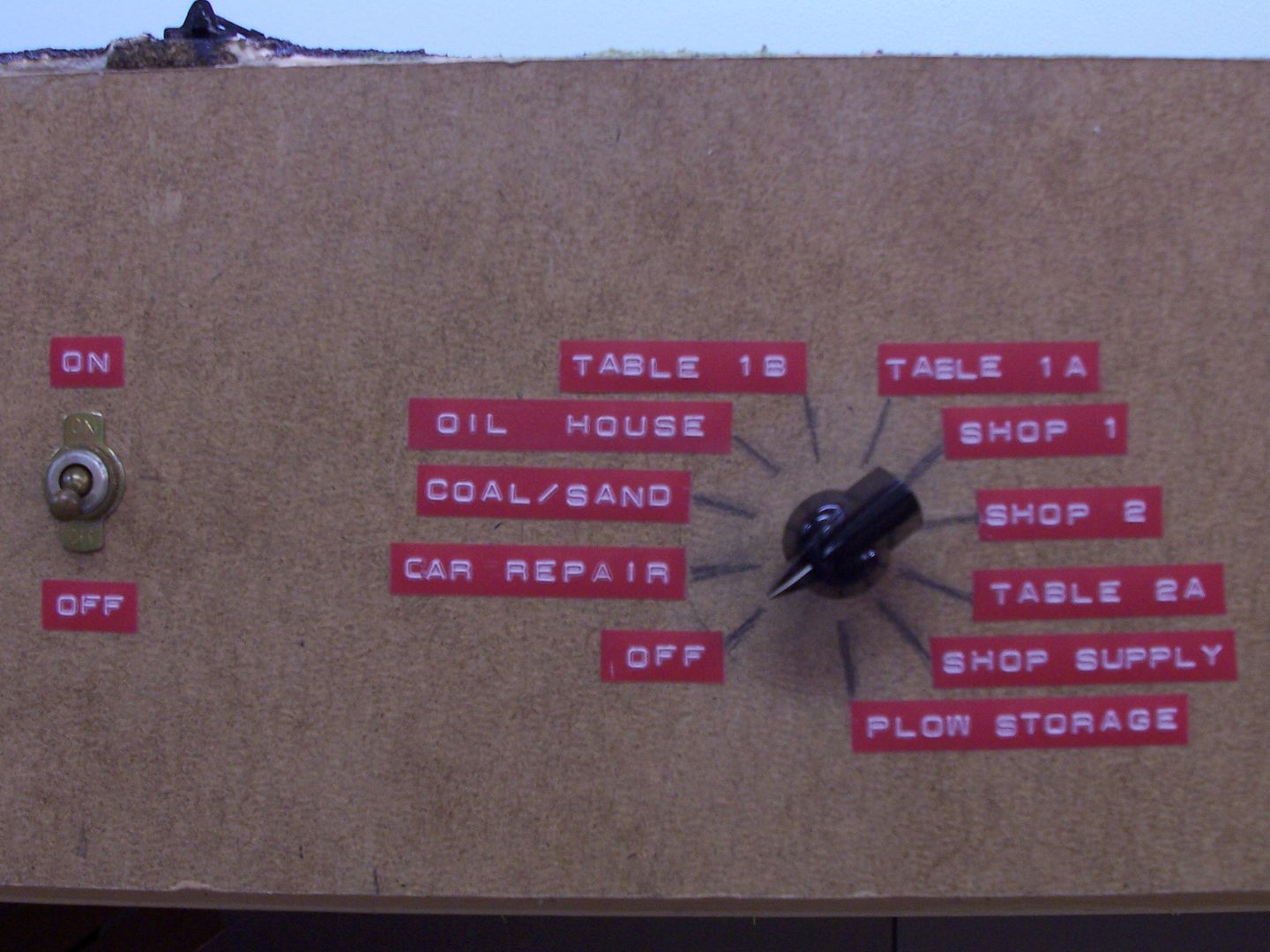
…you could save room by using a similar set-up with a single switch for power, and a rotary switch, with suitable LEDs at each position.
Wayne