Ok, here it goes. It has been a while since i have been on the forum but have a wiring question or questions.
I am in the process of rewiring a club layout, approx 30 x 40 feet room. double mainline with one major yard and a hiden staging yard. There will be 5 digitrax boosters to start located in the center of the room. Each booster will be attached to a terminal strip (one district) so i can run a lot of sub districts from that terminal strip. This way we can add circuit breakers (as funds permit), keep it broken up for trouble shooting and maybe for block detection in the furture.
I was going to try and keep the bus wires to 30 feet max, I was going to use 14 gauge wire.(because we have it) with 20 guage feeders. Seperate each mainline into a district and about 8 sub districts each. Break the yard in to several districts. Use 3M SCOTCHLOK 560N SUITCASE CONNECTORS for 14-18 gauge wire, to connect the bus to feeders. If ii had a bus longet than 30 feet i was going to run 12 gauge wire from booster terminal strip to a terminal strip located closer to the district area and then run the 14 gauge bus from there for the feeders.
Will the scotch lock connectors work with the 20 guage feeders?
should we solder feeders to to the bus wire?
another way, is to run the bus wire to multiple terminal strips and then connect the feeder wires with the fork terminal connectors. Every 6 feet or so
with everything broken up into sub districts, Is 14 enough or should we use 12? I hear a lot of people saying to use 12 or even 10, but i read that 14 was good enough for 30 feet and that 12 & 10 were overkill. also i read that you should not go over 30 feet anyway because distortion of the DCC signal.
Our club has a many years old DC layout with 14 blocks and common rail that has been converted to DCC wiring using #14 buss and #22 feeders. I double over the end of the #22 before inserting the wire into the suitcase connector.
I monitor the voltage in each block with a couple HO sound locos running and we have been good. We have run as many as twelve sound locos but run about six or seven on average. I have a DIY DCC voltmeter in case we ever see an issue so it is easy to check a section for a defective connection.
We do one block at a time. Some people do a complete layout and run into trouble with shorts. Make checks every so often.
I work under the layout and another fellow is working on top in case of needing another feeder and cutting gaps were required. We have two cross overs and use two MRC reverser’s. We run at least four different types of sound decoders in various locos.
A couple of us have electrical experience which helps a lot.
I am rewiring my clubs layout also. We went to DCC about five years ago and didn’t have to make any changes to the wiring. Most of the members are not young so when I began rewiring I made Duct that is on the outside facia of the layout so there is no longer any need to crawl under the layout to do soldering or attaching wires while scrunched up under it. 14 AWG is for the DCC buss. And 20 AWG is for the track feeders. To secure the wires and make connections I used pass through barrier strips from allelectronics.com part #TB 35. No soldering is necessary to connect the feeders and the barrier strips make it easy to add feeder wires or make changes. A new facia is used to cover the duct and looks very nice.
I am a big fan of soldering. Some people swear by Scotchloks, some people swear at them. I believe the one size will do #20 tap into a #14 bus, but they don;t have one that does $20 into #12. The idea of runnign #12 until you get close to the area and the switch over to #14 is a fine idea and should work with no problems.
I have used scotchlok #567 with 12G buss and 20G feeders with no problem. It is a rather small layout, 8 x 22 feet. Am pulling 13.9 volts everywhere on the layout.
personally i say solder everything. i fitted a GPS tracker using scotch locks and first attempt one of them didn’t quite cut through the insulation. i spoke the the company that supplied the kit and they said they prefer soldering themselves because with any movement the scotch locks can become intermittent but home fitters aren’t usally upto soldering so they supply scotch locks!!. i realise there will be plenty of folks that have used scotch locks and are happy a year down the line cos the layout is permanent. but a club layout that may get moved or taken to exhibitions could start to suffer eventually. decent solder joints won’t cause trouble. put the effort in now rather than later fault finding. soldering also looks neater rather than dyslexic lego everywhere.
Our club has a 27’ by 27’ layout(two levels). We have three 8 amp boosters. We ran 12 gauge wire for the ‘bus’, and 18 gauge for the actual track feeders( ScotchLoc 567). There is a ScotchLoc connector for 14 gauge bus/20 gauge tap(905 IIRC) and that is what I used on my home layout. We have had no issues with them. I would suggest you buy one of those expensive ‘crimping tools’ for them - it really is better than using pliers. We have an area when one guy ‘hand crimped’ using a pair of channel locks, and one of the connections failed after 18 months. - recrimping with the ‘tool’ resolved the problem(and I recrimped all of the connection in that area to make sure). I even borrowed the club’s tool and re-did mine(about 150 connections) just to make sure).
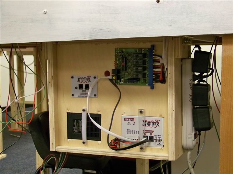
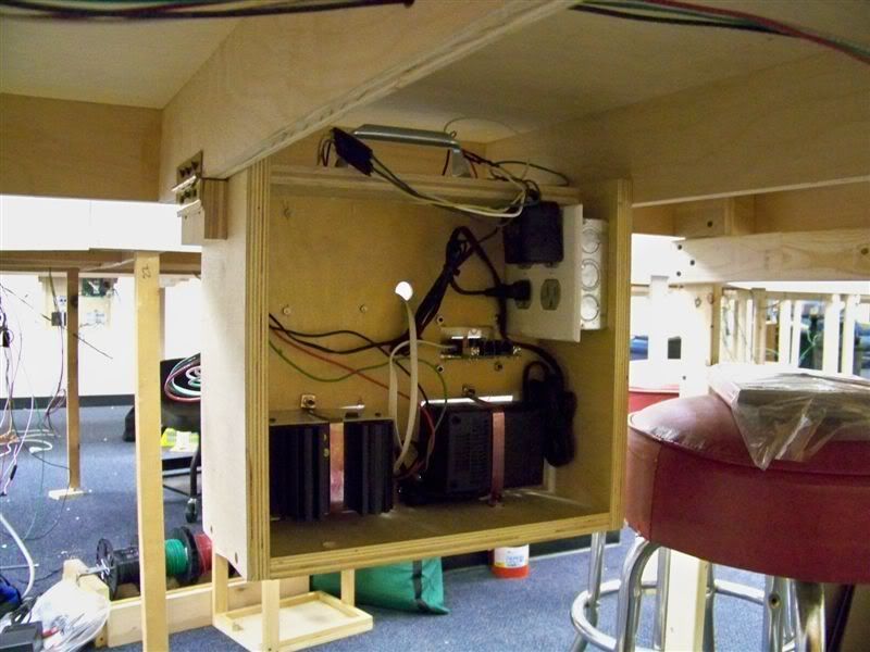
If possible, put the boosters central to the power district they run. Loconet cable can be run much longer than bus wires. Try to keep the bus wires less than 30 feet in any one direction. On our portable layout we fabricated boxes holding the booster, PM42 breakers, plug in panels (one has a UR91 radio deal, one has a LNRP), and power supplies. Pull the plugs, two pins, and it comes out for transport.
We have three, spaced out to be centrally located to the districts they power.
I highly prefer soldering feeders to bus wires. Get a good wire stripper. Scotchlocs are spendy, and I feel less than reliable in the long haul. In some spots we do use spade terminals to a terminal block. Do not just strip wire and run it under a screw, proper terminals are essential.
That is a very nice installation. I am a big believer in neat and clearly labeled. I also agree that the command station or booster should be in the middle of the district it powers.
I have never used Suitcase style connectors. They look easy but I am a little punchy about stabbing into a wire through insulation. I use terminal strips, but I follow threads that discuss other methods with great interest.
Solder not only strengthens a mechanical electrical connection, but also protects it from future corrosion.
In the aircraft maintenance business (my former trade) and on my personal layout, we have a word for electricians who use suitcase connectors:
DE-CERTIFIED!
I personally, use screw terminals (actually stud-and-nut terminals) for my analog DC electricals. If I was into DCC, my bus-to-feeder connections would all be soldered, and painted with liquid insulation.
Suitcases are fine for packing clothes. They have no place on a wiring system designed to be bulletproof. Not to mention that you can buy a LOT of solder and flux for the price of a fairly small number of suitcase connectors.
Chuck (Modeling Central Japan in September, 1964 - with bulletproof electricals)
I figure there are about 3 trains on each mainline, with a minimum of two locos on each train, plus a few in locos in the yard. Most everything has sound and there will be additional ones just idle with sound. lets say 25 max.
i have heard that the suitcase connectors can fail, but mostly in situtations where they are exposed to the elements and movement (cars) thinkgs like that. these would be under the layout not really any movement. i also prefer to put feeders every 3-4 feet not 6. if one does fail i think we should be covered. I also believe that you should not count on a rail jointer for conducting power. feeder to every rail that is not soldered together. I was also going to leave a little extra feeder wire. we could always come back and solder or put in another connector if needed.
i believe that you wire one section, test and then move to the next. this also keep the layout or most of it operational
this brings up another question. if people are using teminal blocks, wouldn’t you have the same contact as a suitcase connector. A terminal is just a screw pushing the the wires together and the suitcase pinches the wire with the little metal piece . seems like the same sort of contact.
i do like the idea of putting the boosters in different locations. My layout at home will be like that. but i think they will all have to be together at the club layout.
thanks for everyones input, it is helping i am feeling that i am moving in the right direction.
I have a 18x16 foot layout around a two car garage. I have 14 engines, 4 of them with sound, 8 lighted cars, and 8 DS-64s that are , for the moment, powered by the track. All that is powered by one Digitrax command station with no boosters.
My track power connections are all stripped wires with spade connectors under screws on barrier strips.
My switch and light connectors are European style strips.
A suitcase style connector has to be sharp because it has to pierce the insulation and make contact with the wire within. That is what makes me nervous. The contact is sharp and the contact area is therefore very small. I can’t say whether or not they work well, because i don’t use them. I am just stating why I don’t use them. I like the large surface area of the spade connectors under screws.
i totaly agree with to many boosters, i have only been with the club since the first of the year and that was the way they had it. they were using boosters as districts, and when they wanted another district they would add a booster. no circuit breakers. since we have them i was going to use them. my thought was to get some circut breakers to break it up. might try it with four boosters and see how it works.
do you solder the spade connectors?
actually the suticase connectors are not sharp, the metal is the same width on the whole piece. it is just that the insulation is soft, so it has no problem pushing it away and making contact with the wire. it doesn’t cut the wire either if you use the right size. stranded maybe one strand.copper is soft and as you push the metal connector down on the wire the gap actually spreads. is a tight connection. the reason i know this is when i first got them, i used one and then open
I like the DS-64s very much. Two of mine are powered by PS-14s, the rest are track powered. Eventually they will all be powered by PS-14s. I make extensive use of the ability to run routes.
I like to strip the insulation on my feeder wires back about 2" after using the stripping tool to remove approx. 1/4" to 1/2" of insulation
on the buss wires i wrap the feeder wire (solid core 20g bell wire) around the now exposed buss wire. hit it with some flux on a micro brush and solder the connection. I like to wrap the connection with colored electrical tape indicating the same color used on the buss wire it’s connected to.red/white. a good solder connection will never fail. When I see a car or a bike come into my shop and I spot suitcase connectors it spells out AMATEUR
I think its good to remember that most outlets are wired with 14ga wire protected by a 15amp fuse or 12ga wire protected by a 20amp fuse. So, since your outlets/wiring wont handle anything more than 20amps(with 12ga)safetly, using anything larger is really overkill. You definetly want to check your circuits before plugging in all those boosters, + whatever else you might be using. I bring this up because my electrical teacher has told us many, many of horror stories of how people have wired circuits. THis is assuming that you havent looked over the breaker box yet of course. Voltage drop isnt a big factor unless your talking about really large layouts, but I went with 12ga for my buse even though 14 was probably just fine. I have my DCC system approx. 34ft from on end and 46ft from the other, although this may change before the layouts finished.
Comparing the ampacity of low voltage house wiring to that of extra low voltage train layout wiring is like comparing apples to oranges. Lose 10% of voltage due to wire length on a home lighting circuit and most people wont notice that the 100 watt bulb now being lit with 108 volts is a little dimmer. Especially if they’ve never seen it brighter. Lose 10% on a 12 -15 volt rail bus and the command DCC command packets will no longer be reliable.