Weight of Cars

I have eight empty and eight loaded iron ore cars. Between op sessions I restage them to where they should be.

At the club, the coal cars are unloaded at their destination, and the load place back at the mine. The same with pulp and paper log loads, scrap loads from the scrap yard, etc.

You can run most weight cars but if you got cars of differnt weights, then you have to place them as the real railroads do. I have some light as can be cars (no place to add weight) and some extreamly hevey cars that I bought as a lot one.

The weathering on this interior turned out so well that I could not put the intended load in the gondola. I managed to put a 1/16" thick sheet of roofer’s lead underneath the floor, and the car comes in at 4 ounces! Success.

The GREAT SOUTHERN, at least as originally built, was completely flat. It was double track mainline that ran point-to-point in a purpose-built outbuilding.

Lorell Joiner was one of my early inspirations in model railroading. In my innocent youth, I had no idea he was wealthy, and everything he did was beyond normal means.

I need to add a GREAT SOUTHERN freight car to my fleet. I saved your picture to my “ideas” file.

All of my hopper cars have permanent loads in them. I do not like the look of empty hoppers. I can suspend belief long enough to remove the still-filled hopper car from the coal dealer.

Gondolas and flat cars… it depends on the load.

I have some that have heavy loads, and the car and the load are permanently mated. This cast resin load by Chooch is permanent in this gondola. The load casting weighs almost 2 ounces, so it is part of the total running car weight.

For some others, the load is very light, and the car can be weighted to full weight, and the load can be removeable.

These two electric motors weigh less than 1/4 ounce, so they are remov

Alyth Yard said: “Pushing cabooses up mountain grades just wasn’t the practice. The underframes of cabooses couldn’t take the loads.” It depends on the era, location, and equipment. Steel-framed cabooses on some roads could be used ahead of helper engines.

From the stories I’ve read, the crews in the cabooses really hated that. The caboose would slam left and right on the rails from the force of the pushing locomotive. Scared the crew half to death. And the noise!

Yes, most steel cabooses, if not all, could be pushed against.

Some cabooses had “do not push” instructions stencilled stating the caboose would need to be cut in behind the pushers. I have seen one wooden caboose that was built on a steel boxcar frame that had “OK To Push” stencilled on the carside.

I do not think pushing against cabooses was an unusual practice.

I can only imagine… I would not want to be in that caboose.

-Kevin

The B&O adopted steel cabooses early on and always pushed them so that helpers could be cut off on the fly.

It typically took four big Mallets to get 100 cars over Cranberry Grade, stopping at the top was not something anybody really wanted to do.

I have lots of pictures, just not in digital form…

Sheldon

A caboose with a steel underframe was at least as strong as any other car in the train, so if a railroad chose to put the pusher ahead of the caboose, that was up to them.

I prefer the pusher(s) behind the caboose, as it’s easier for the conductor to simply pull the pin after the grade has been conquered, allowing the pushers to return to their regular spot, waiting for the next train that needs some help.

Wayne

I learned an interesting fact watching the History Channel. While the Rockies are he tallest mountains in the US, the Appalachians are the steepest. They would have the most difficult grades.

Somebody explained this to me a long time ago but I’ve forgotten the answer. What was the advantage of using pushers and mid-train helpers as opposed to double or triple heading a long, heavy train?

Coupler loading is higher if you add pushers to the head of the train.

Pushing from behind the caboose puts the locomotive drive forces through the underframe of the caboose.

Cutting into the middle of the train reduces both types of forces. However, cutting into the middle would be more challenging to coordinate for the engineers during the steam era.

MU diesel, especially robot radio controlled, provided the capability to solve the mid train coordination issues. Of course, mid train locomotives are now commonplace, not just in pusher service.

Yes, the Appalachians are “steeper” in general than the Rockies, making it harder to survey reasonable grade rail routes thru them. The grades are steeper and the curves sharper.

Like Mike said, coupler drawbar forces. As curves get sharper and grades increase, coupler drawbar stress and force increase.

A rear train helper pushes the back “half” of the train while the front loco pulls the front half

[quote user=“ATLANTIC CENTRAL”]

John-NYBW

ATLANTIC CENTRAL

The B&O used their 2-10-2 Santa Fe type, known as the “Big Sixes” since the whole class was numbered in the 6000’s, on their other route west thru Pittsburgh.

The curves on the MD/WV old mainline were too sharp for them - they tried one once…layed it over on its side!

That’s why smaller drivered articulated locos were so popular in the eastern mountains. The mountains here might not be as tall, but they are still pretty rugged in terms of finding rail routes thru them - again, nothing but curves, often pretty sharp ones.

Sheldon

I learned an interesting fact watching the History Channel. While the Rockies are he tallest mountains in the US, the Appalachians are the steepest. They would have the most difficult grades.

Somebody explained this to me a long time ago but I’ve forgotten the answer. What was the advantage of using pushers and mid-train helpers as opposed to double or triple heading a long, heavy train?

Yes, the Appalachians are “steeper” in general than the Rockies, making it harder to survey reasonable grade rail routes thru them. The grades are steeper and the curves sharper.

Like

I use the NMRA standards as a starting point. When a car derails more than a couple times and I can find nothing wrong, wheels in gauge, etc, I start adding weight. This usually fixes the problem. And they do run better.

Several of the outdoors type stores have bins full of lead fishing sinkers of various sizes, sold by the pound. These can be hammered or squeezed in a vise into whatever size or shape you need. Many can be glued into the underframe of various cars.

The issue is perhaps less coupler loading than draft-gear loading – not to disagree with the point. In the era we’re talking about, cars were smaller and draft gear more primitive, and this was a notable problem with a number of attempts to build larger articulated power or electric locomotives – the Triplexes and the PRR 2-8-8-0 and “Big Liz” FF1 being notable cases in point.

Therefore train lengths became significant as well as loads, and using midtrain helpers would keep ‘sections’ of cars from exceeding critical slack shock loads that might snatch a drawbar rather than just a knuckle… or from being pushed out of alignment severely, or even lifted, or in some cases popped right out of line or damaged, when in buff.

I’m sorely tempted to tease the previous poster by asking ‘how do you have pushers at the head of a train?’ but we understand what he meant. Note that there is different behavior between ‘helping’ (where the train won’t make it without the additional engine power) and ‘snapping’ (where the train runs at higher speed or lower time thanks to the increased power, as on PRR passenger trains over Horse Shoe). The latter is always, in my experience, done from the head end even though it would be more difficult to drop the helper at the end of the ascending grade, for good reasons.

I did some experiments with a 71 car train (most cars somewhere near the NMRA weight recommendations), using four Athearn switchers, like these…

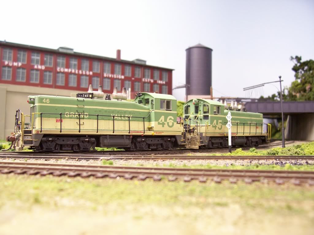
…and four Bachmann Consolidations…

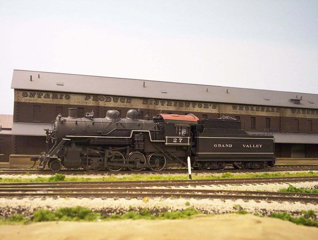
…with all 8 locomotives having added weight.

I ran the train using the four diesels in various configurations: four on the head end, then two on the front and two on the rear, and all four distributed fairly equal throughout the train. I then repeated the process using the Consolidations, and again using a four-engine mix of steam and diesels.

The grade is 2.8%, laid out over two horseshoe curves, followed by a series of “S”-bends, and is about 45’ in length…some of it is shown in the photo below…

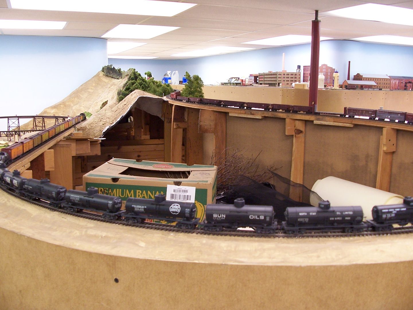
…when the track ended at the top of the grade (the partial upper level hadn’t yet been built)

(the train shown is not the test train)

What I found was that the train was moved successfully, regardless of where the locos were placed within the train, or which combination of locos was used.

I also noticed, when running the same train on other parts of the layout, with two locos leading and two pushing on the rear, and also with all four on the front (most of the layout has a varying up-and-down profile) the run-in and run-out of the slack, when first noticed, verged on terrifying to see. Different parts of the train were moving almost like an accordian, although there were no derailments.

All-in-all, I was both surprised and pleased with what I learned. I don’t normally run trains of that length

I’m sure that in prototype practice care was taken to try to ensure that the lead locomotives pulled the “entire train” to some degree, including the mid train or end train pushers. In other words, the pushers mid or end train would power up enough to reduce coupler loading but not actually push the couplers …

If so, then that would explain why the CPR preferred to “push” from the front. A broken coupler mid train would not be good…on 4% grades especially.

Well, in the known example I explained above, the rear helpers would indeed be putting as much of the train as possible in compression and pushing it, while the lead locos would be doing their best to run away from the pushers.

Remember, the examples I gave are from the 30’s thru the late 50’s with steam or steam and diesel combined. And as explained there would be two locos on the front. The first one trying to drag the second and that one trying to drag the train, or at least the first half.

Same on the rear, maybe a set of diesels with one engineer, or again two, or even three steam locos.

No radios, no GPS, no computers, just whistles and the seat of your pants feel. Crews at the rear could only go by feel, brake air pressure readings, and whistle signals.

Trust me the couplers moved in and out from tension to compression the whole time.

But the whole idea is that the weight of the whole train was never fully on one coupler while they were on the grade.

Those guys were engineers.

Sheldon

From what you have shared, roads in Canada clearly had a different view of this, since for one they never had large power like the US roads.

I have no practical knowledge of railroading in Canada beyond what you have shared.

But here, crossing the Appalachians, big articulated locos and lots of them was the answer for many roads.

Sheldon

CPR built some 0-6-6-0 pushers around 1900 for the Big Hill at Kicking a Horse Pass, where the Spiral Tunnels are now. They were interesting in that the engines faced each other under the center of the boiler. They were later converted to a successful 2-10-0 design which lasted pretty much to the end of steam if I recall the data correctly.