Why the change from the Walthers #6 to the “NMRA” #6?
My guess would be that the “NMRA” are shorter, so as to maintain the 2" spacing.
It looks like, very roughly, one picks up 11" more yard capacity with the lower design–a nominal two cars.
Ed
Why the change from the Walthers #6 to the “NMRA” #6?
My guess would be that the “NMRA” are shorter, so as to maintain the 2" spacing.
It looks like, very roughly, one picks up 11" more yard capacity with the lower design–a nominal two cars.
Ed
If you look at real railroads, in tight spaces they try to put the points of the next turnout as close to the closure rail of the previous turnout as possible.
Our model track components can’t do that, they need lots of track in between to maintain structure, but ME tries to as much as is feasible by making some of the components as stumpy as possible.
If you could stack the points one after the other, you could have broader radius closure rails (and the same radius beyond the frog) and an upright ladder that doesn’t take up a lot of linear inches. Those are the real goals here, broad radius with little length.
As long as the closure rail radius is broad enough (as well as the embedded radius of the whole shmear including point rails), what the resulting frog number happens to be is tertiary.
I made the graphic a long time ago, so I don’t remember why. But you’re right, apples-to-apples would have been better – and one would probably need to trim the Walthers to use them with curves as shown with 2" spacing. But since folks (OK, one folk) expressed confusion about how it worked, I just posted what I had on-line already.
It’s a terrific graphic, and I’m glad you posted it. It does give a very good sense of how it works.
I did a bit of calculating, and came up with shortening the Walthers switch by about 2.1" to keep the 2" spacing. There’s about 3.6" available for removal in the Walthers turnout, so should be no problem.
Ed
One of the things I like about Peco turnouts is they are already very short, the likihood of needing to trim them is much lower. But I’ve trimmed Atlas and other turnouts as needed to get them to fit.
I seem to have missed this, but what’s then length, nominal radius, and ‘source’ of the little pieces of curve inserted to make the trick work?
is there a source for making up a template or gauge to form this curve in flextrack connected to each ‘shortened’ switch, which might make this simple ?
In the past I have just made it with flextrack in N scale, it would also work for other scales. I use the minimum radius I have chosen for the yard (which might be different from the rest of layout). How much curve depends on the length and frog number of the turnouts that you choose as well as track spacing of the yard tracks – to me it’s a little bit of trial-and-error.
About 2-3 degrees of curvature added to the diverging leg of the first turnout has often worked well for me in designs for others – and then the corresponding curve on each yard track.
That is a distinct advantage of Peco over Atlas for a turnout - - 3". Peco is 9" in length whereas Atlas is 12" in length for a Code 83 #6 turnout. That can be crucial when space is at a premium.
Rich
Comes in an assortment of radii and lengths.
Ed
It all depends on the degree to which the turnout ladder is angled relative to the alignment of the parallel straight yard tracks. You place the straight and parallel yard tracks where you want the yard. You place the first turnout at the required angle. Then all the connecting curved pieces are just like any other series of concentric curves. That is if you want a neat and tidy result. If you want to optimize the total length of the sidings in the available space then you create the curves you need and they won’t necessarily be nested concentrically.
I’ve always been struck by the paradox that the outermost curve of parallel or roughly parallel tracks should have the tightest radius to maximize track length but the broadest radius if you want the track to look correct.
This assumes the first turnout is from a mainline that is not parallel to the yard tracks where the mainline first diverges but eventually lines up.
For a yard and mainline that are parallel to begin with then the siding curves are the same length and radius as the reverse curve coming off the first turnout. The first curve sets the shape and length of the siding curves.
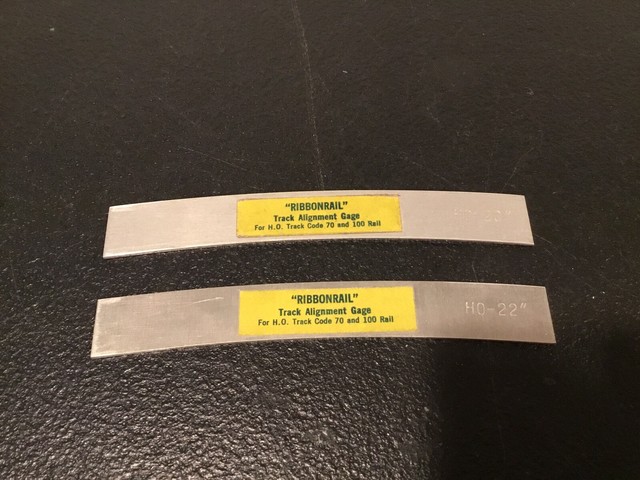
Ed, those are worthless for the short curves and their transitions that are being described here. Does the company make a special short ‘transition’ gauge for these ladders? They should…
I’m well aware of the theory; I just saw it taught again. I’m also aware of the theory of the coaxial escapement. In order to actually build either, it is helpful to have methods and dimensions, not advice to kinda-sorta curve stuff to fit and live with any glitches.
I suspect cuyama could produce a template comparable to the transition spiral in MR that could be printed off, cut in thin sheet or whatever, and used to set this track by track.
And that is because…
Ed
A gauge facilitating laying the small curves involved here would have to fulfill all four of these, whereas the ones pictured can’t do any.
(If there’s anyone who knows where to find a single gauge that does what’s needed, I’d expect one of the Eds would be the one to know…)
One could do this for one specific combination of turnouts, radius, etc., but it’s not something that is one-size-fits-all.
Of course, if one chooses not to go to the trouble of laying this out with flex, one could forgo the small increase in yard body track length and just use the stock turnout angles.
Yes, and the current situation (involving the stock #6s rotated to a steeper angle but preserving a given track spacing) can be used as the example.
They are aluminum, and can be cut to length in under a minute. Filing the edges of the cut smooth might take weeks, of course.
See above.
Because these curves are so short, there is no room to have an easement (transition). In addition, it would be wise to use a fairly wide radius curve, so as to lessen the stress on backing movements through the switches. And this also lessens both the need for and the possibility to make an easement (transition).
The real problem with putting in these micro segments of curved track is to not have a kink at either end. To that end, it would be wise to solder a length of flex to the diverging track, and bend it to shape in place. That should eliminate the kinking possibility.
Done.
Ed