Looking for some help, new to model railroading (HO). I have very limited space in my home so I’m out in the garage with my new layout, 4x8 2" dow blue foam board (dense), and a 1x3 plywood frame (made from 1" 1/4" cabinet sheeting (left over from new home). The 4x8 by itself weighs 51 lbs. I have mount Unistrut on the ceiling to carry the load across the ceiling joists, and currently using a 4 pully system on each corner. The issue I have now I raise the platform together (each side with two ropes), the other end rises followed by the end closest to were I’m standing, so I work each side up with a little assist on one end and its ok. Looking for a better idea, that works woth out all the assist and leveling??? Pics are worth a thousand words. Thanks
I’m sure you’ll get better responses from the real engineers out there, but FWIW, a couple of modifications suggest themselves, which might make your life a little easier.
I’m assuming from your description that you have 4 independently hoisted corners, each with it’s own independent pully. You might be better served by making a “Y” yoke at each end and having only ONE rope at each end. This way you’d only have to deal with the side-to-side levelling. If you ran the cables together to a common spot, you could lower both cables at the same time and wouldn’t have to deal with running to each corner and lowering a little at a time (think of a venetian blind and how you lower that).
Also, if you used steel cables instead of ropes (the kind used for garage doors), you can put a bolt on the cable to act as a stop, so each side would always go down the same distance and would be level at the bottom.
A commercial four-pont lift may show you some ways to solve the problem. Check out Harken Hoister: http://www.hoister.com
Their user manuals are on-line as .pdfs.
My system that works quite well using a 3/4 inch water pipe for a drum with a crank on one end and a level wind device to prevent overrides on the 3/32 wire rope. It lifts 220 pounds with ease through a vertical distance of 5 feet. As soon as I can figure out how, I’ll post a picture.
I’m going to advocate that you consider an alternative to your raise-away plan and go to a plan using an A-Frame setup to suspend your platform. Fold the platform 75-90° to the floor and roll out of the way when not in use; suspend in a horizontal position when in use. Admittedly this has the inconvenience or requiring all rolling stock be removed prior to storing.
Engineering anything which must be raised poses an engineering challenge in the first place but if you persist: 1) do away with your multiple cranks and devise a system using only one crank so everything moves in continuity–with multiple cranks no matter how carefully you try to be everytime you raise one corner you are going to apply torque someplace; and 2) get rid of the ropes and use steel cables instead.
Of course you could do what a model rail once did when his layout space–garage–had to share the facility with that other life’s necessity–automobile. He had his layout platform just high enough off the floor to clear the hood of the family car. The car was pulled just far enough into the garage that the rear bumper cleared the garage door and the grill cleared the layout at the front.
Didn’t it pose a hazard to the layout if the car is pulled forward too far? That happened–he of course threw the blame on the wife but who are we to know?–but it did prompt him to suspend tennis balls from the overhead joists. When the tennis balls hit the windshield that was time to STOP!!!
Sorry for the double posting and the general mess I’ve made of this presentation. When the picture was finally posted this is the only way I could figure out how to show the explaination.
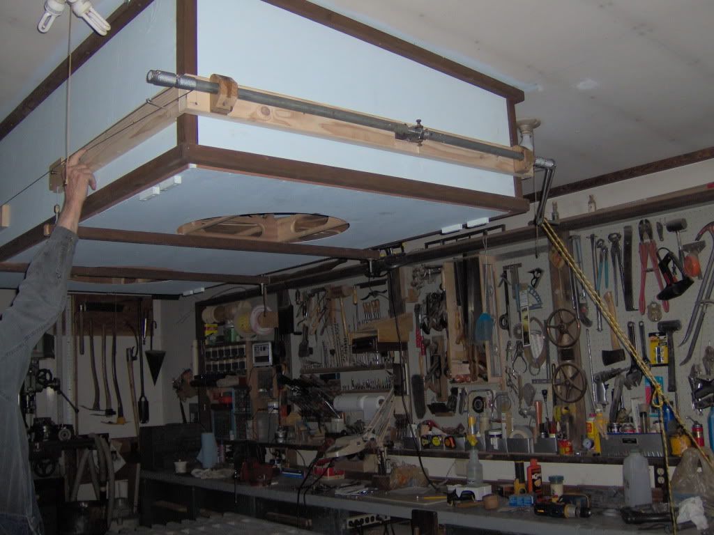
In this view of the stowed position, the four (two on each end) evenly wound wires are shown on the pipe. In the center of the pipe is a short section of threaded rod and the nut which is fixed in place and causes the rod and pipe to move laterally through the oak block bearings as the crank is turned. Even winding on the pipe is essential to prevent overrides of the wire causing one corner to raise faster than the others. Just to the left of my hand you can see one of the turning blocks and the attachment to the support bar which carries the load.
Geohan
My last suspended HO layout used a small boat trailer winch to crank it up and down from the ceiling. On my current layout, I’m using 12V marine actuators to turn the whole layout sideways for storage.
MR had a brief article on this back in the dark ages (1960’s I think). The key points that I recall were:
Four cables with spring clips connected to loops at each corner of the layout.
Each cable ran through its own set of pulleys, for each - one pulley directly over the respective layout corner, the other pulley over the common counterweight at (possibly within the stud space in) a nearby wall. Obviously the pulleys must be well secured across several structural ceiling joists.
Each of the four cables individually connected to the counter weight with a turnbuckle to permit adjusting the length.
The counterweight was a metal can filled with concrete with an embedded pipe handle at the top for the cable connections and was slightly lighter than the layout. I’d suggest an inverted U of pipe where you could add fitness weights on the verticle sides secured with a pipe end cap.
When the layout was in the stowed position at the ceiling, safety hooks at the ceiling prevented accidential lowering. I’d suggest one or more cable clamps placed on the cable between the spring clip and its overhead pulley to act as a stop so that scenery wouldn’t be crushed against the ceiling. (Gee, why do all my trees have flat tops?[D)])
To lower the layout, release the safety hooks, guide the layout down, place a sturdy board-shelf under the counterweight (on brackets) to support it in its elevated position, slide a separate saw horse under each end of the layout and disconnect the cable spring clips.
One would need to recognize that weight and potential energy of the layout and counterweight can pose a significant safety hazard which would require careful construction utilizing suitable materials and techniques.
This sounds like a really good and simple system. The only thing I could add is to make sure that the pulleys’ diameter is a least 20 times the diameter of the wire and that the wire is multi-strand, say 7x7, to avoid fatigue and failure.
John Armstrong suggested that the counterweights be made adjustable, like cinder clocks or sand bags in a box, so that it could be changed as the layout grows heavier in construction. Of course, if the original poster’s layout is essentially done, the counterweight can be figured once.
As mentioned, the counterweight system doubles the load on the celing attachment points – no place to scrimp.
The discussion in Armstrong’s Creative Layout Design (Kalmbach, 1978, sadly out of print) is pretty thorough, but the book may be tricky to find. There was also a good article on a large layout built in this fashion in Model Railroader, June 1977, page 52: "The Midland Valley RR, hanging layout in 3 car garage " by Jim Hediger.