Hello. I have maybe a mid-1990s Proto 2000 that’s DCC ready with an 8-pin, 2-row socket. And… like a dummy, I pulled out the plug without looking at the orientation. Can someone tell me which pin is #1 so that I can put my encoder in the correct way?
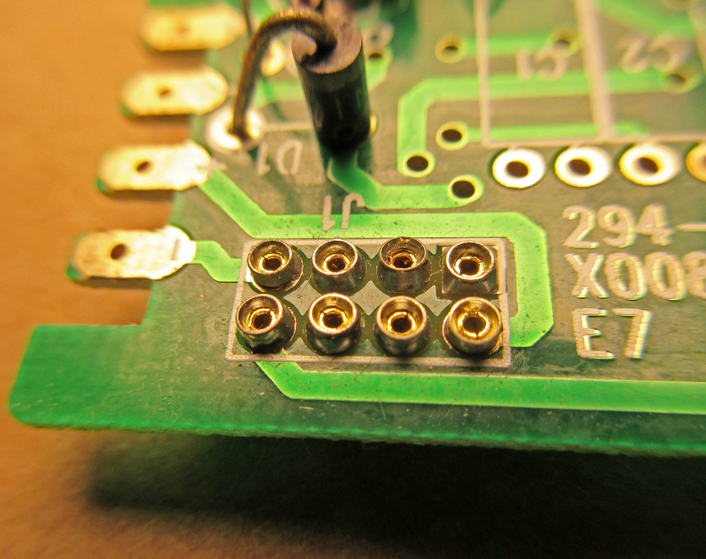
My plug is at the very aft-end of the engine (just in case there are different versions). Right by the socket, the board reads 294-X008 E7. There is a deceptive “J1” on the board by the row cloest to the front, poart side, second column, but this can’t be Pin #1.
Ya, based on my experience, no matter how hard you study the issue, the decoder will go in the wrong-way around about 75% of the time. Not worth losing sleep over, just plug it in and try it. As Randy says, if it goes backwards when it should go forward and the lights don’t work, remove it and rotate it 180 degrees.
If you study the socket very closely you will see that one of the solder pads (top row, right) on the board is square, the other 7 are round. Normally this would designate “Pin 1”. Sometimes there is a little triangle pointing to it with screen-printing but this is not the case here.
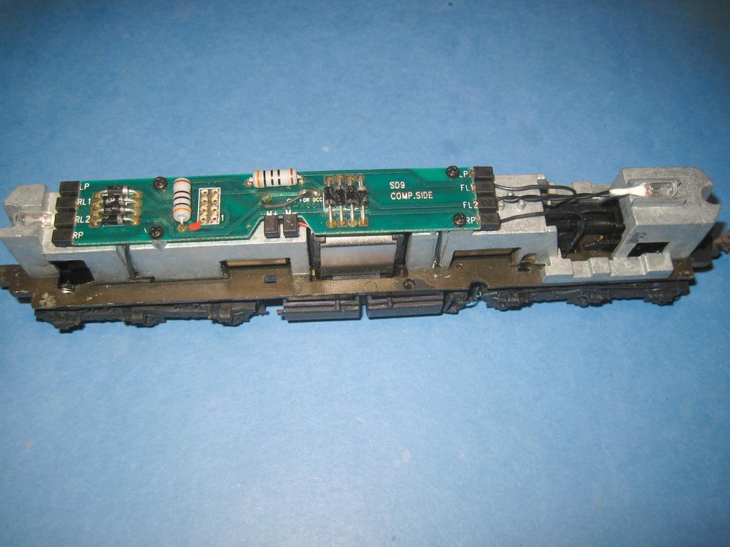
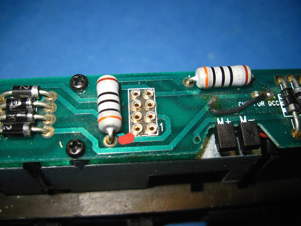
My Proto SD-9 has a 1 next to pin 1. When I first started into DCC I put a red dob of paint next to pin 8 on all of my 8 pin NMRA connectors for quick ID.
Use of something like “J1” is a common convention on circuit boards for either ‘jacks’ or ‘jumpers’ – in either case where something external to the board is going to be plugged in. Usually the numbers refer to specific jack/jumper-socket locations, not to wire arrangements or numbers of wires in the connectors themselves. On the other hand, I’m familiar with connectors having at least some of the pins/sockets overmolded having identification of numbering by at least a couple of digits (cf. the typical 40-pin IDE/PATA hard-drive connector) where there is potential ambiguity…
Lest you think this connector layout is a weird anomaly, see this discussion of the matter from stackexchange.com which, in the comments, explains why the numbering in the socket part of the connection runs as it does.
So why didn’t the designers use keyed connectors? Pet peeve… I once raised a stink with the board designers at work about not keying the connectors on prototypes. I shouldn’t have to get out the schematics to check connector orientation. It costs $0 extra.
Because they didn;t have to - backwards doesn’t break anything. They are just off the shelf connectors, the NMRA didn’t design them or anything. You plug it in, see if it works, if not, slip it around. Nothing is damaged.