A 2-6-2T Engine for the Bradford Valley Lumber Co. (On30 Mogul Kitbash)

Hi all,

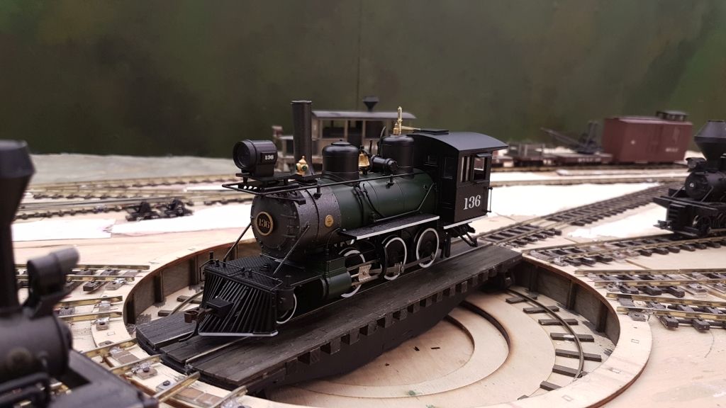
I decided to build a new locomotive no. 8 for the Bradford Valley Lumber Co, as I wasn’t satisfied with the current one (a 35-ton diesel critter). I’ve always liked the look of the Bachmann On30 2-6-0, however as you can see below, the locomotive itself already takes up most of the turntable.

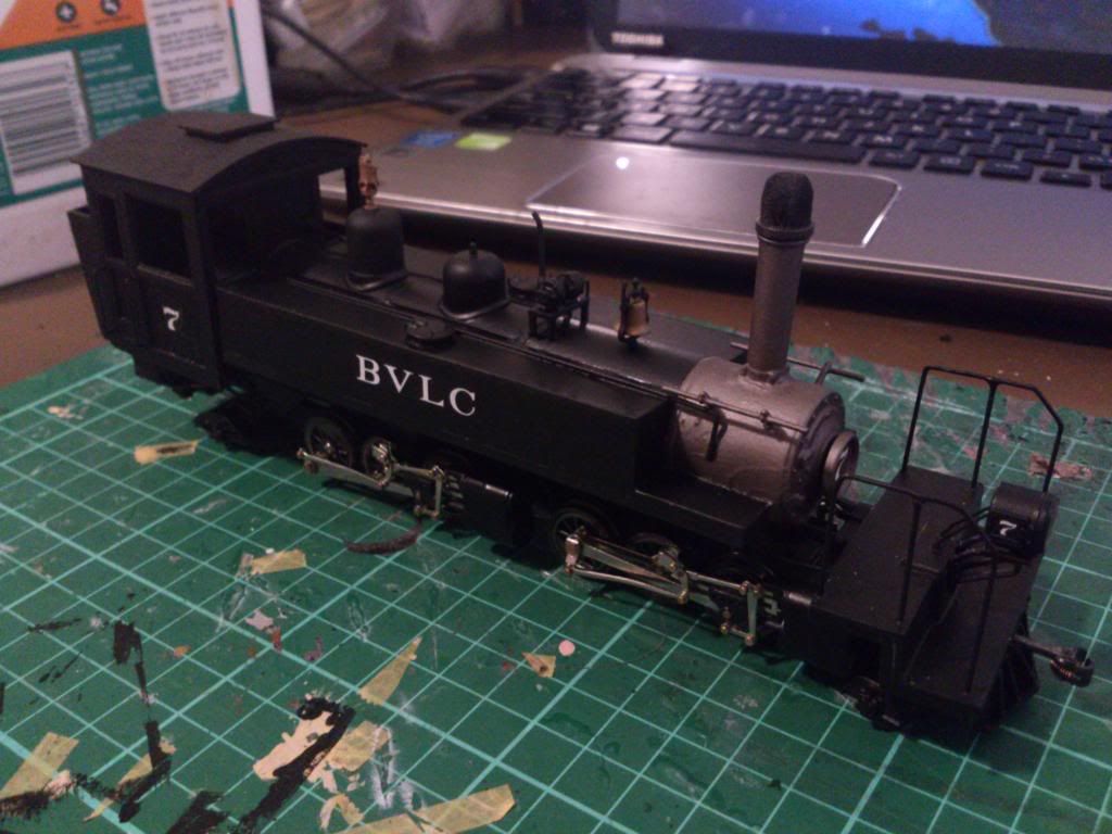
As such, I decided to convert it into a 2-6-2T saddle tank engine. Although not following a particular prototype, it’s inspired by this Alco engine: http://narrowmind.railfan.net/262T-ALCo30-42.jpg.

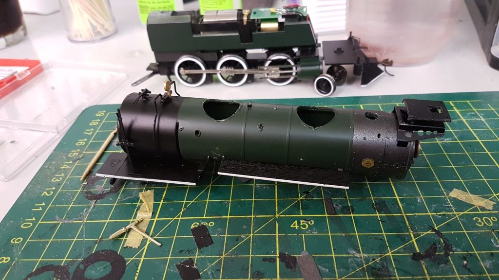
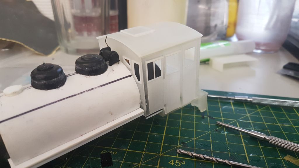
After figuring out how to get the shell off, I removed the domes and other details. These were put aside for later use.

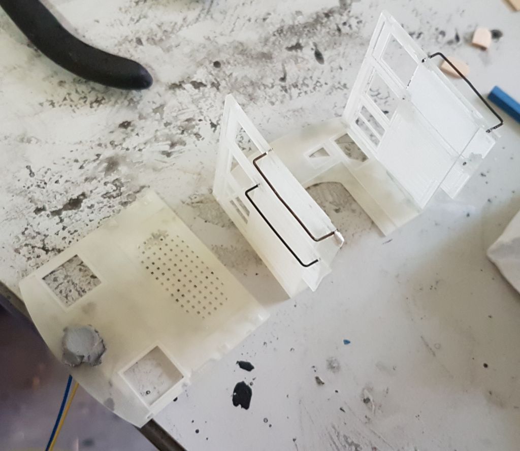
My next step was to construct the saddle tank. On the original model, there’s a short section in front of the cab where the running board is at the same height as the cab floor, then the rest of it runs a bit higher. As such, my original plan was to have the saddle tank stop at the end of the higher section, then bring the cab forward to meet it.

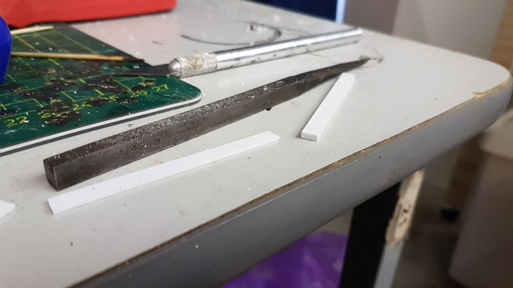
I obtained some 4cm diameter PVC pipe. After cutting that to length, I cut it in half lengthwise. The resulting pipe was a little bit low, so I decided to raise it by about 5mm. To this end, I used some 3mm x 1mm and 2mm x 1mm styrene strips. I glued them e
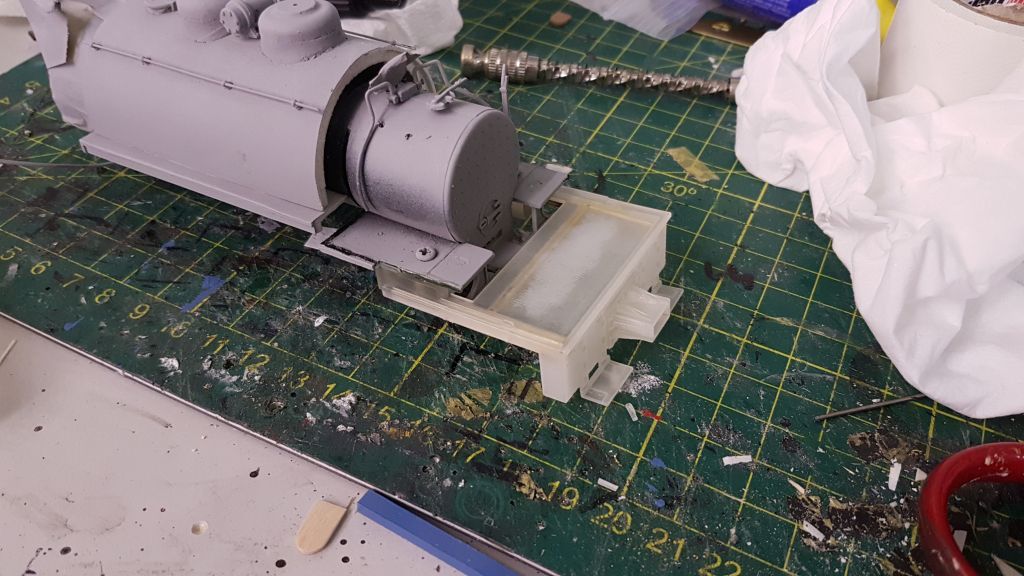
Hey tbdanny!

Very interesting project!

You are very brave. I’d have a hard time cutting into the original 2-6-0 but you will end up with a unique locomotive. I’ll be curious to see how the 3D printed cab turns out.

Dave

That surely looks like a fun project, especially in O scale. I look forward to progress and final photos.

Another option for the water tank is side tanks instead. It might be easier. Though, if you’re following a prototype or just like saddle tanks, that’s different. Anyway, my first steam loco was this little fella (as an example of a small side tank loco):

It’s HO by the way. Made by Tenshodo. The only one of their products I could afford at the time.

By the way, the biggest “flaw” in the model is that it only picks up on two wheels on the left side (middle and rear). If you ever get one of these, be sure to add another pickup for the front wheel. And/or a keep alive.

Nice work!!!

Ed

Ed,

I have done a side tank model before, the original no. 7 for the BVLC:

However, I ended up having to do them three times over and they were slightly uneven. I also liked the look of that saddle-tank prototype, so I decided to go with that this time.

Yup.

Nice little fella.

Ed

That saddletank looks really good, and it looks like it’d be a good place for some extra weight if your operations would benefit from such an addition.
Personally, I prefer headlights on the smokebox front, but you’ve obviously got a “look” in mind, and I’m looking forward to seeing it. Very nice work. [tup][tup]

Wayne

Looks really good, tbdanny! Those unhappy results previously were good learning experiences and it really shows here. Looking forward to seeing things finished and painted.[:D]

BTW, Bruce Pryor’s site is a great sources of inspiration for anyone needing something a bit different, like logging, mining, or other similar application.

http://narrowmind.railfan.net/

If you have pics of any export loco built in North America, he’d likely be interested in hosting it. I’ve got one of my pics on there. Best we could tell it’s a GE U?B:

Hi all,

As I mentioned in part one of this project, I decided to use 3D printing via Shapeways to have the front pilot and cab made.

I have made 3D models of locomotives before, for Trainz Railroad Simulator. This is where I follow my interest in British railway modeling, in ‘V scale’, so to speak [:)]. Amongst these models were a few tank engines, and I realised that I could adapt the same techniques I’d used for their cabs to make this model.

I started with the front pilot. On the Bachmann Mogul, the cowcatcher is held onto the front deck by two small screws. As such, I decided to make a ‘switcher’ pilot, which would be a screw-in replacement. To this end, I measured the dimensions of the cowcatcher, and re-created the rear clips, screw holes and panel in Blender. Once this was done, I measured a Kadee No. 5 coupler box and created a ‘dummy’ one in Blender, to aid with construction.

Blender does measurements in what is called ‘blender units’. They are to no particular scale, and so one blender unit can represent one foot, one metre or one millimeter, as needed. For my Trainz models, I usually use one blender unit to one metre, so no scaling is needed when exporting for the simulator. For Shapeways models, the unit is specified when you upload the model. As such, I worked with the scale of one unit = one millimeter for these Shapeways models.

Once the rear panel of the pilot had been created, and the Kadee box positioned correctly, I started creating the front of the pilot. I started with the coupler mount, making it 1mm thick around the Kadee box. I added a 2mm hole underneath, to allow the mounting screw through.

Once that was done, I added the two steps at the front. I originally had these

tbdanny:

Thankyou for that very interesting insight into developing a 3D printed model.

Dave

Huzzah, I agree, Dave.

tbdanny provides a great example of what the future of this hobby looks like. Sharing a project on a global scale via the internet, developing parts, and then making them available through Shapeways and other means.

Sure, there’ll be RTR, but those folks lamenting the loss of kits should consider they are becoming more of DIY project, either finding parts already available that are useful or developing new parts that then become fodder for the projects of others.

Part 3: Misadventures in 3D Printing

At the end of my previous post on this build, I mentioned that I had designed the cab and arranged for it to be 3D printed by Shapeways. About three weeks after my first post, I received the first version of the cab kit and pilot:

Unfortuantely, there were several defects with the models I received.

I had designed the new pilot to be a ‘drop-in’ replacement for the 2-6-0’s original snowplough, and I had copied the mounting pegs and screw holes from the original Bachmann part. These were an exact fit, and I was able to screw the pilot onto the front of the pilot deck without any issues.

However, the coupler box on the front was 0.6mm too narrow. As such, I had to remove the sides of the Kadee coupler box in order to get it to fit in. When I tested it with another locomotive, I also found that it was too low. I fixed both these issues by narrowing the inside coupler box walls by 0.3mm each, and raising the coupler box. Doing this allowed me to put an extra row of bolt details underneath the coupler, as well as enlarge the bracing underneath.

I then test-fit the cab to the locomotive. The cab walls had been designed to be approximately 1mm

tbdanny:

The pilot looks great!

Interesting trials and tribulations! Thank you very much for taking the time to explain all the little glitches. I’m sure you must be a bit frustrated by them but seeing you work through them is very educational. Your costs must be mounting a bit though with having to do parts over again.

Thanks for sharing!

Dave

Dave,

The costs aren’t too bad. Shapeways actually refunded the first model, as it didn’t turn out properly despite being within the tolerances for the material selected (Frosted Ultra Detail). Also, due to the turnaround time (~3 weeks), the costs are spread out.

On top of this, Shapeways actually allows its users to sell their models to others, and I’m planning to do so with these. I’ve already made the pilot available, and I’ll be doing the same for the cab kit and smokestack once I’ve confirmed they’re correct.

Hi all,

After a few months working on the build, on-and-off, I’ve completed BVLC No. 8. It wasn’t as straightforward as I thought it would be.

At the end of part 3, I had just realised that a minor correction needed to be made on the cab walls.

Once I’d received the new cab parts, I installed the cab floor as per the last time. I added some brass bar to reinforce it.

Like last time, I formed grab handles out of bent wire. However, this time around I ran into a bit of a complication. For some reason, the corners of both side walls broke off when I went to drill through them. In order to repair this, I used some styrene and body putty to fill in the gaps.

With the grab irons in place and repairs done, I then assembled the cab. Before attaching the rear wall, I added the rear headlight, which had been recovered from the previous cab.

I then attached the cab to the body, and ran the headlight wires into the cab, under the floor, then up next to the firebox. The idea was to have them out of sight under the cab, then disguised as boiler piping when entering the body shell.&nbs

tbdanny:

Outstadning work !! … [bow] … Thank you for sharing.

tybdanny,

Makes for a husky looking logging Prairie, a real classic of the woods.[:D]