Most of us with layouts larger than 4x8 examine our final track plan in light of much advice and shake our heads about how much track we squeezed in despite the advice of experts. A few actually did minimalist track plans. Both groups can still find themselves in need of an extra track or two for operational reasons or just car storage.
But where to put this much needed track(s)? Real estate along your layout’s ROW can be expensive. Old buildings can be in the way and your Family Planning & Zoning Commission may reject overly optimistic plans.
In my case, adding track was for operational reasons. I needed it to support needs I had not anticipated whem I designed the layout. This can especially be the case with a first medium to lareg size layout. You discover operation schemes not anticipated or newly interesting you want to duplicate.
In three examples I found success in adding track to the outer lip of the existing track along the top edge of the fascia. Two involved wood and the thrid was foam. I’ve been thinking about doing an article on this, as I took many step-by-step in-process pics. Not sure I’ll pursue that or not. This may be a bit too much carpentry, at least right now. Gotta save for track right now, so you’ll have to use your imagination right now, but more pics will come.
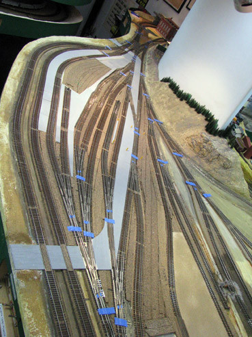
Before
I needed at least one more siding, but I was able to make enough room to add another long single-ended track, too.
There is of course a trap for young, and not so young, players, Mike, as on the various club layouts I’ve been involved in, I’ve come up with some cleverly built extensions to allow for extra tracks as requested by the membership only to find that we ran out of reach to the rear tracks.[banghead]And don’t even mention the fun scenicking back there!!!
Cheers, the Bear (older but not necessarily wiser)[sigh]
Adding that extension must make that lower level really claustrophobic now, no matter how many strings of super bright LEDs you hang under the new extension.
And since the reach to the back issue has already been covered (unless you got one of those Micromark “Flying Man” Topside creeper), do you still have enough aisle width for people to get by without sucking in their gut every time?
Remember, this is narrowgauge, so objects are smaller than they appear…[;)]
Oftentimes, the OCD nature of the hobby emphasizes the “perfect.” This idea simply addresses the all-too-common imperfection of human decisionmaking. Obviously, if we were all perfect, there would be no need for this technique. It can also be used intentionally and designed into one’s original planning. This would be particualrly useful for those with a relatively high second or a third deck, as it could provide additional clearance for shoulders and elbows in tight aisles.
So setting aside the perfect for the practical…
What really counts here is the technique, not whether this is an ideal site to use it, so let’s not get too hung up on that. I’ll note briefly why there’s really no aisle issues.
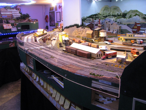
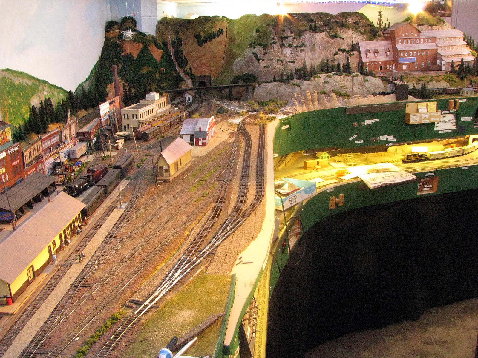
Truth be told, the lower level was originally designed simply as staging. It was pretty claustraphobic down there already. I’ll grab a pic later showing it with the lighting on. The pic doesn’t show it, but the decks in the area with the extension are actually staggered, with the lower one projecting out somewhat underneath the upper. In fact, with LED light strips, the underside of the extension could serve as a mounting place to better illuminate the lower deck.
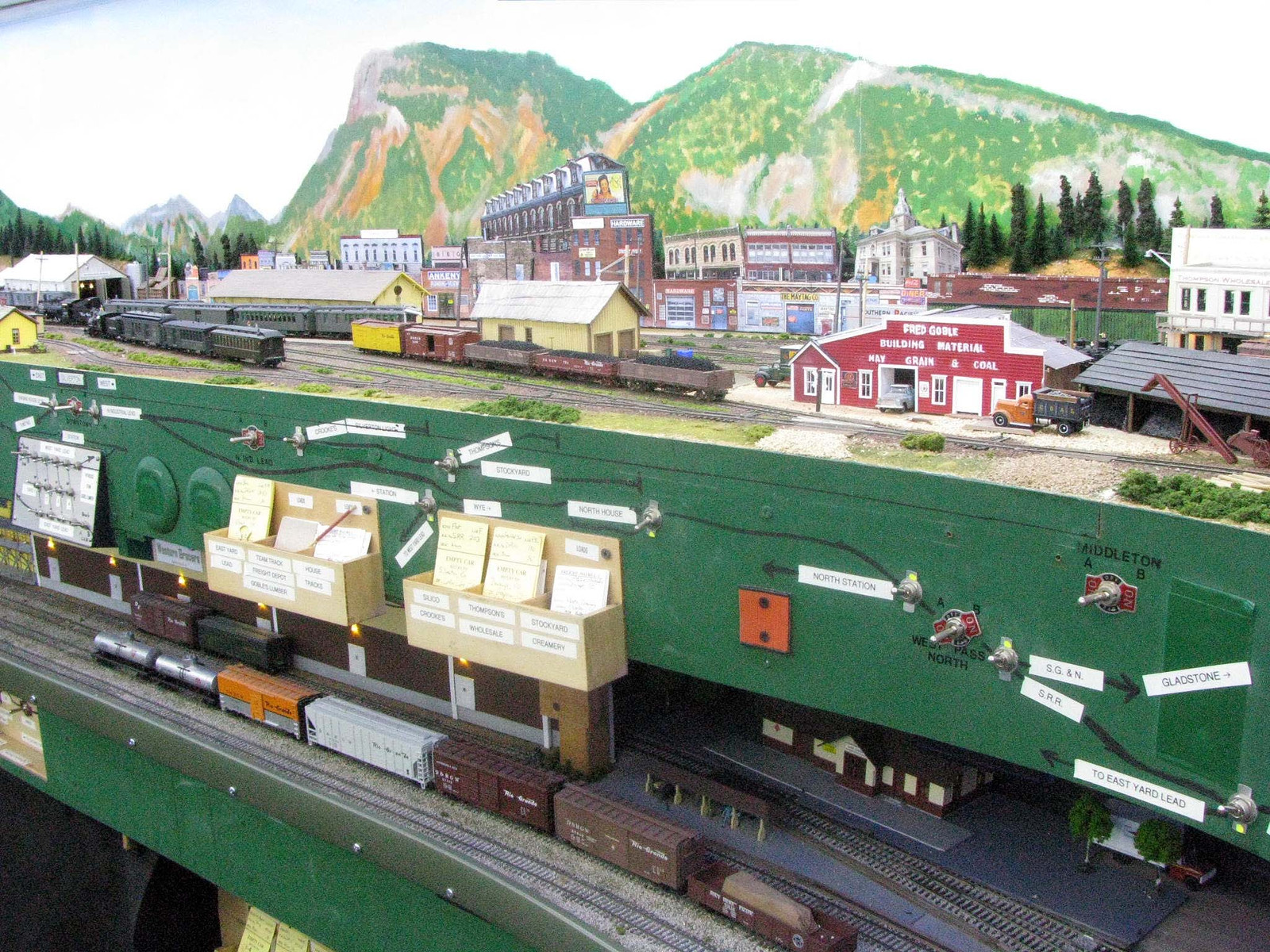
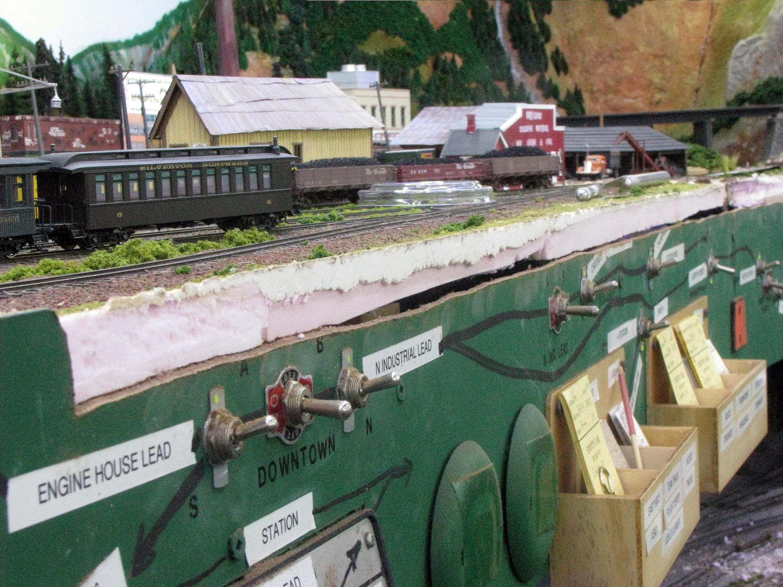
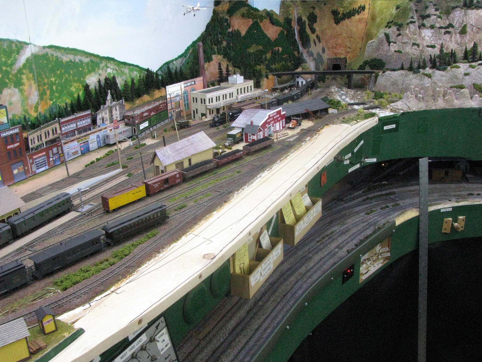
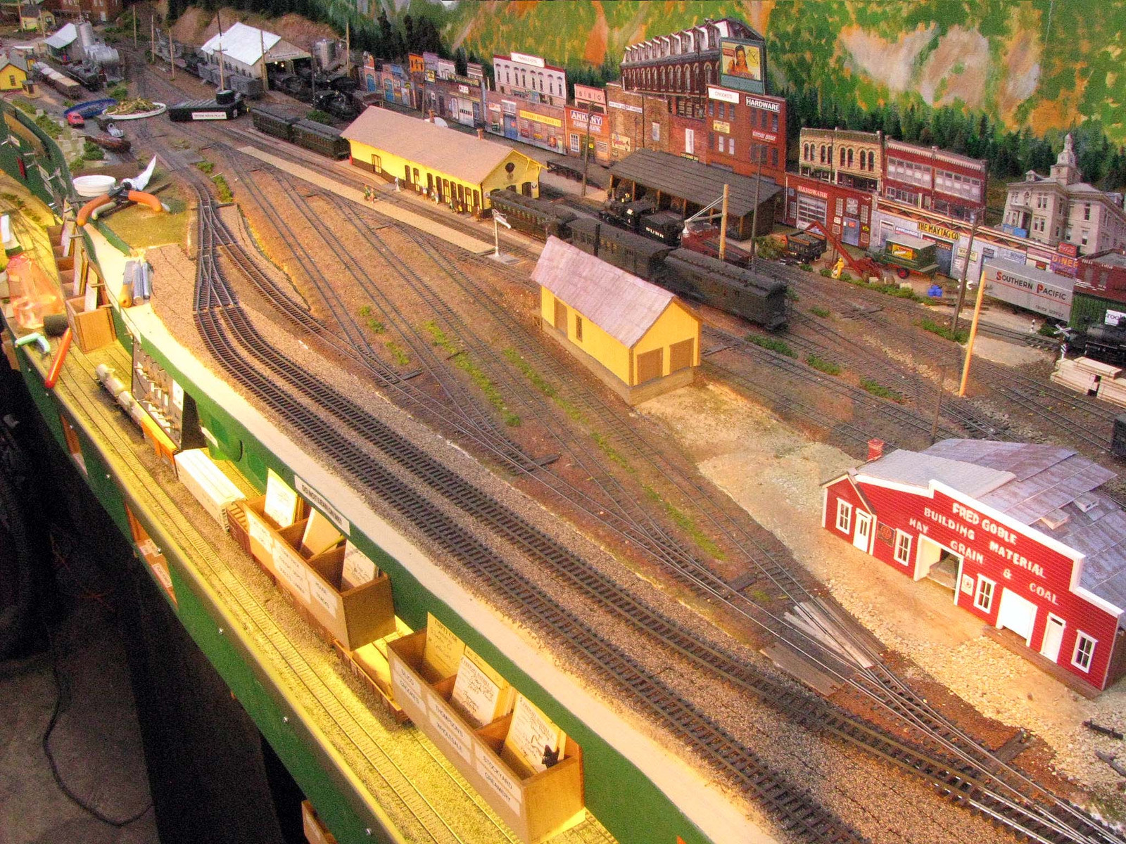
In effect, I’m taking advantage of air rights here. It’s too high up to have a problem with wayward elbows. Shoulder room for shorter people is modestly affected, but this is the wide part of the aisle. Moreover, the locations of card card boxes and the control panel for the yard trackage all protrude outward in this location, taking adavantage of the air rights already.
In fact, I extended the left side curved transition a bit in order to provide some protection to the yard control panel, which tends to get bumped when things are crowded. The car card boxes underneath extend in front of the fascia about 1.75" here. The maximum extension is only 1" more, @ 2.75".
Grabbed some pics to illustrate my discussion above…
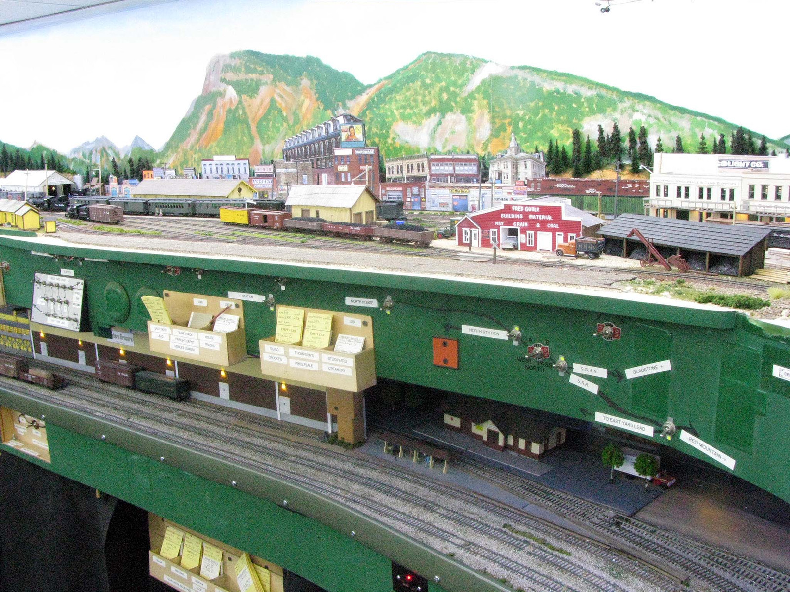
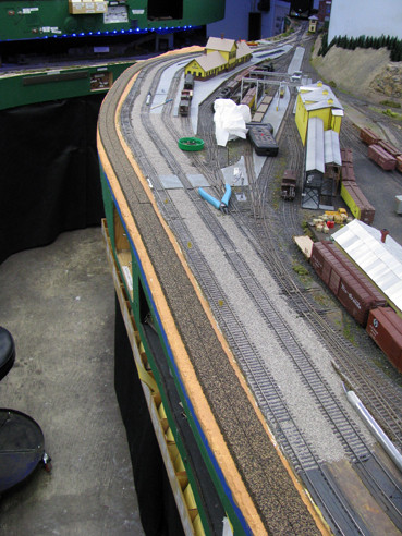
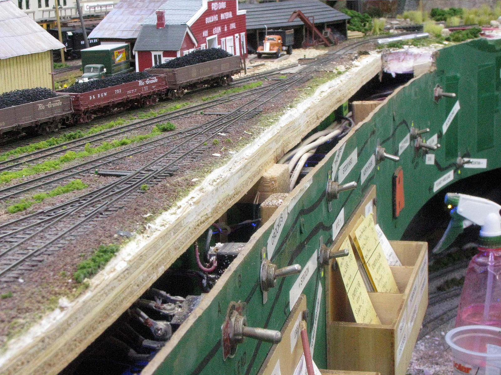
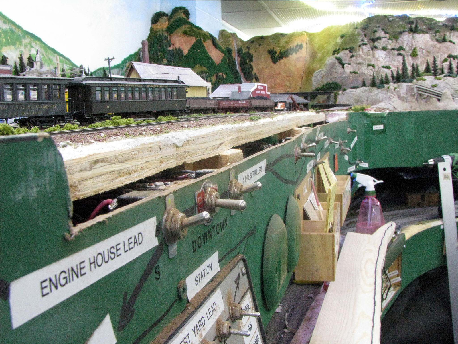
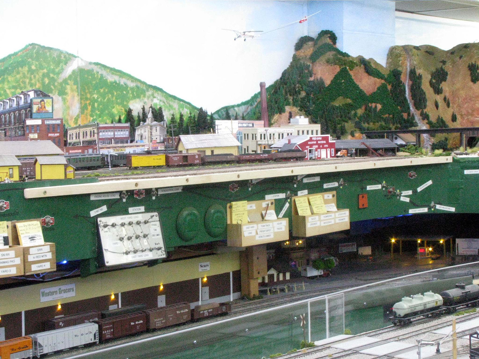
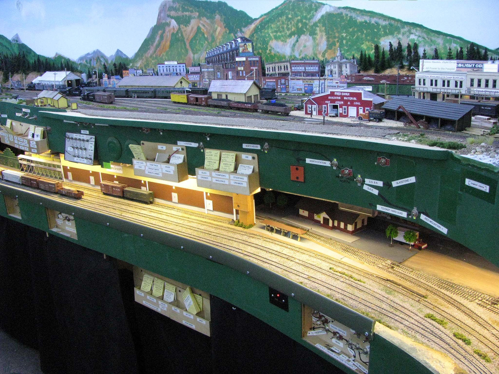
Here you can see how the extension doesn’t project past the lower deck. Whether or not that is desireable in a particular situation depends on a lot of things like aisle width, deck height, etc. Here, with the extension, the two decks are basically even.
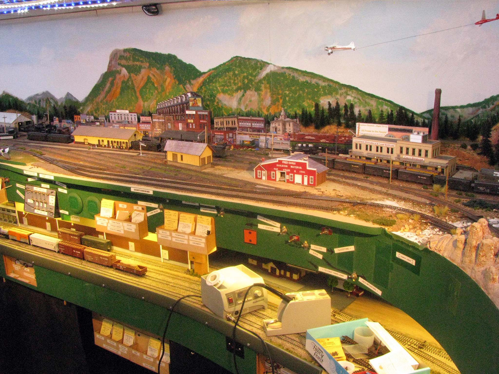
Paint helped a lot in making the extension visually blend in with everything else.
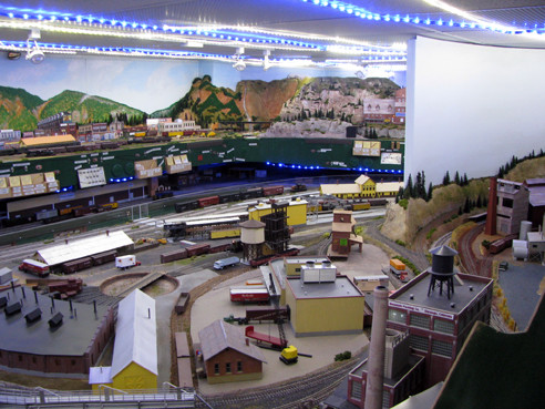
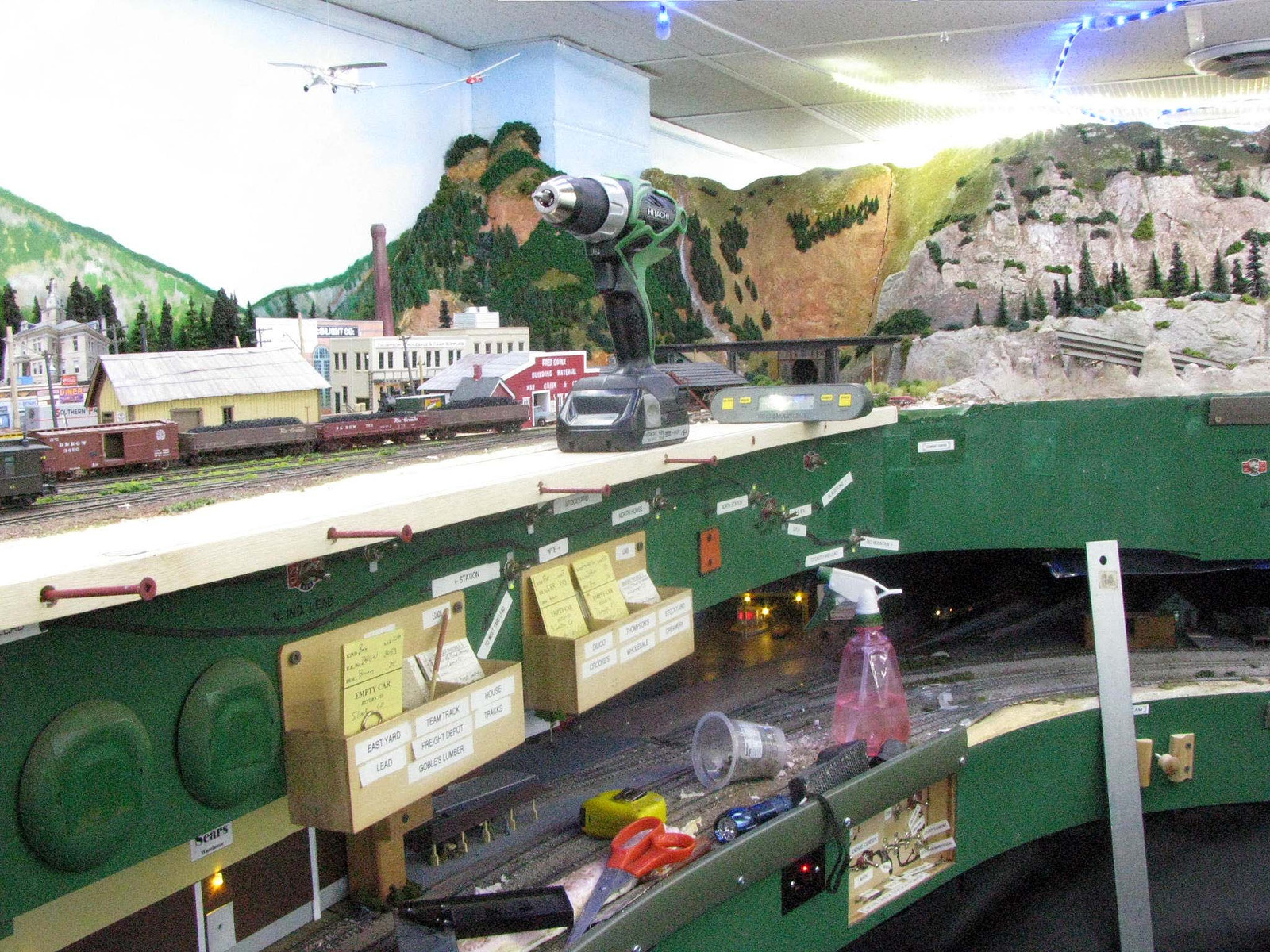
Turning on the lower deck lights, currently tubes but eventually will be upgraded to LED light strips, dispells any gloominess down there.
Deck separation distance here isn’t optimal. Scenicking and industries just sorta happened as the layout progressed and I wanted some more operational interest on the standard gauge. But the extension doesn’t take anything away that was already available. Once I have track laid, the yard capacity in Silverton will be at least 16 cars+. The additional trackage will also facilitate making and breaking up trains to meet the needs created by increased traffic on the Cascade Branch.
Good point on the fascia. This was the first section of the layout that I completed that was really “busy” with various switches, etc. I went in something like three different directions and it is particularly cluttered. Since I had the paint out for blending in the extension, I decided to repaint some of the worst offending “graphics” and labeling and give that a do-over.
I went with the “everything on the fascia in front of what it controls” philosophy, because I generally disliked the idea of control panels sticking you in one spot, which was even a bigger issue with DC control I used back then. I wanted walkaround control as convenient as possible. I just would have done better with more experience. .
Using an extension somewhat uniformly around the layout could serve as handy resting spot for throttles, equipment removed from the track, ops papwerwork, tools, etc if designed in from the start. One of my NMRA colleagues uses a sloping fascia for this purpose, does OK for tools, etc although it’s not going to work for rolling stock. I’ve also seen similar “shelves” located under the fascia itself or in its middle somewhere. Obviously, none of those will help you much if you need some additional ROW, though.
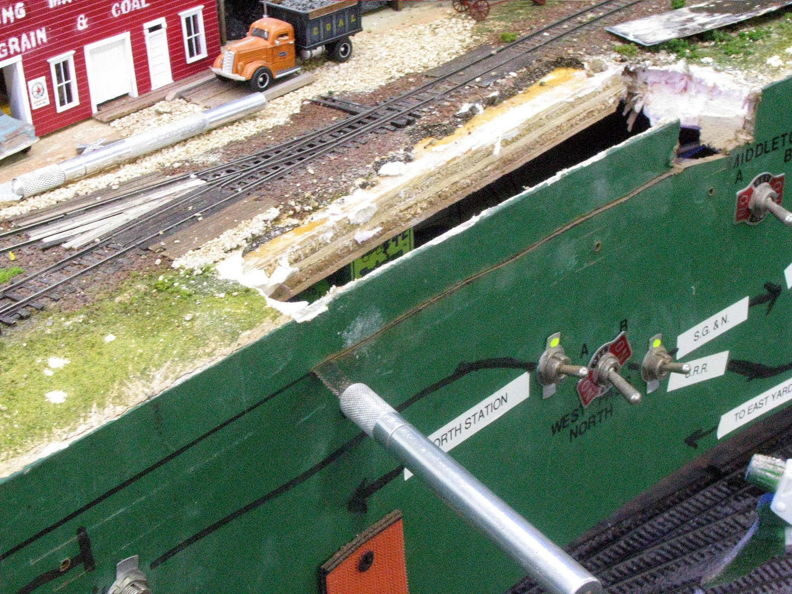
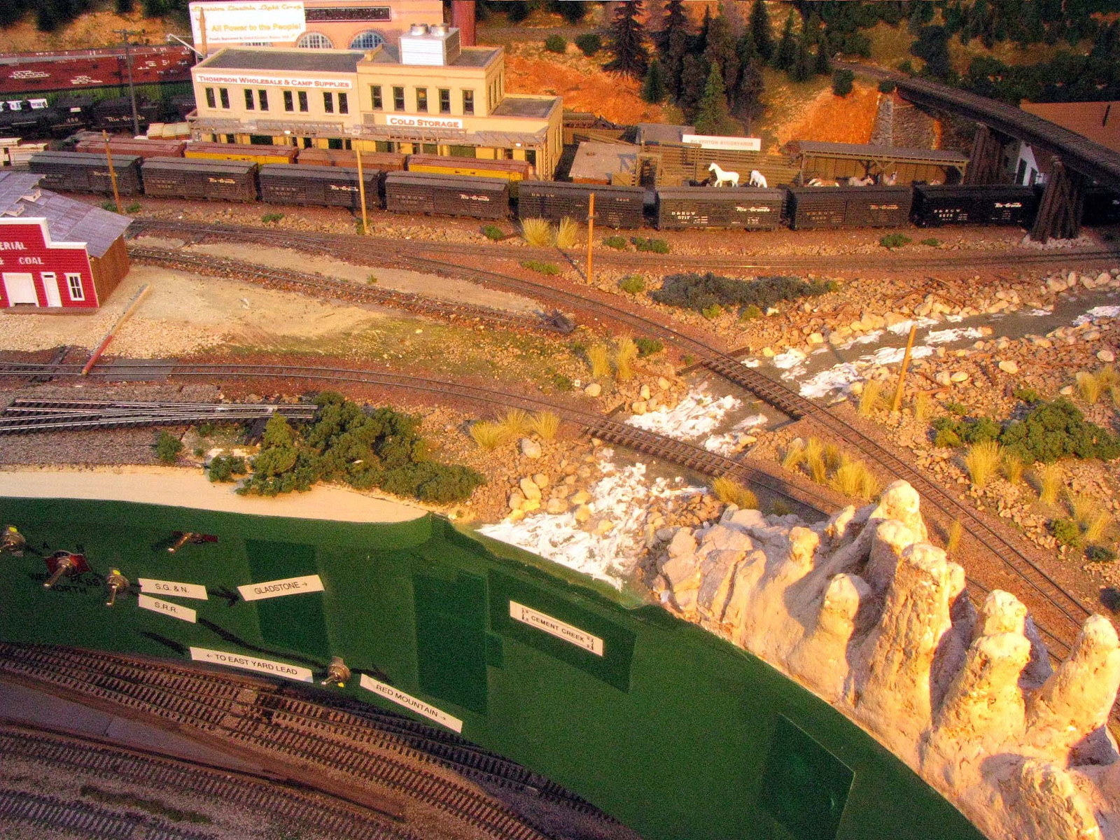
Here’s a peek at the other major “renovations” I made to squeeze in another track near the layout edge, a place where people often don’t think of or fear to use. This one includes a solution to that fear. It’s also the one I did on foam?
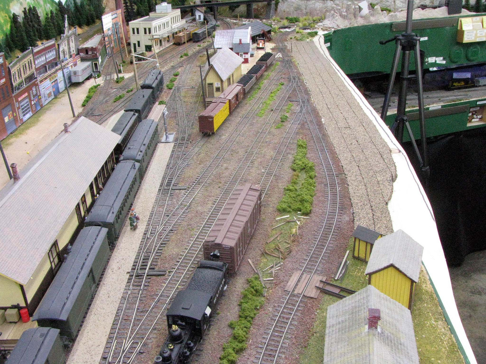
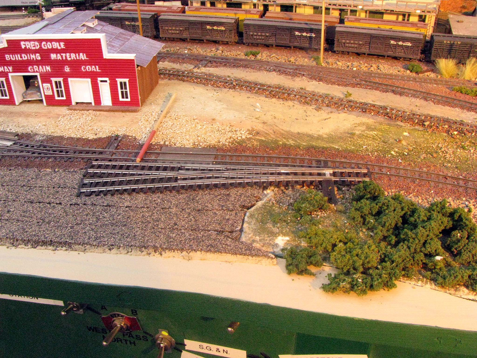
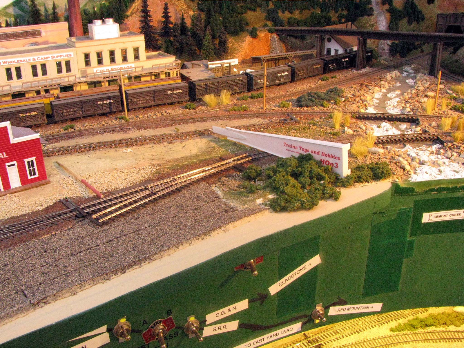
Before: You can see a stretch of ground about 4" wide to the left/aisle side of the tracks that run by the station location in Durango. There’s plywood under the tracks, but foam in between that and the fascia.
After: Basically, I relaid a smooth path of Sculptamold for the subroadbed, then glued cork down. Not optimal, but works without any problems here with the foam glued to both the fascia and subroadbed.
Here, it’s low enough that elbows and guts can be a problem, even before things got “close to the edge.” The local plastic shop worked up a protective barrier from plexiglass. Looking across the layout, it has a low visual impact, largely because it’s just about car height and the deck height is relatively low at the yard.
With the guard in place, I actually worry less now when folks are over than I did before, even though the track is closer to the edge than before. Now it doesn’t matter.
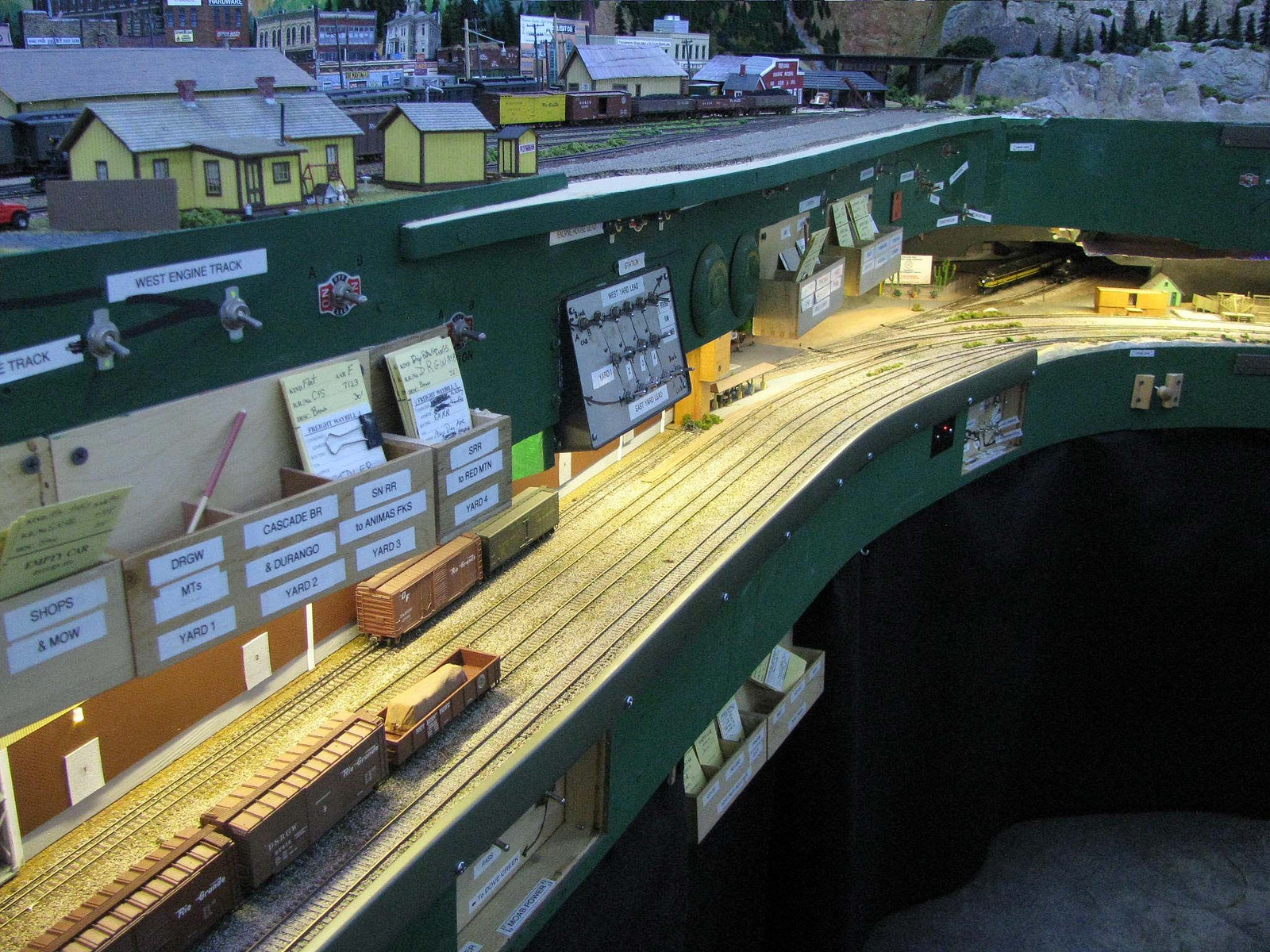
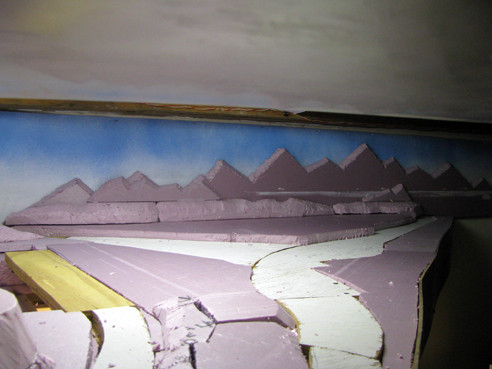
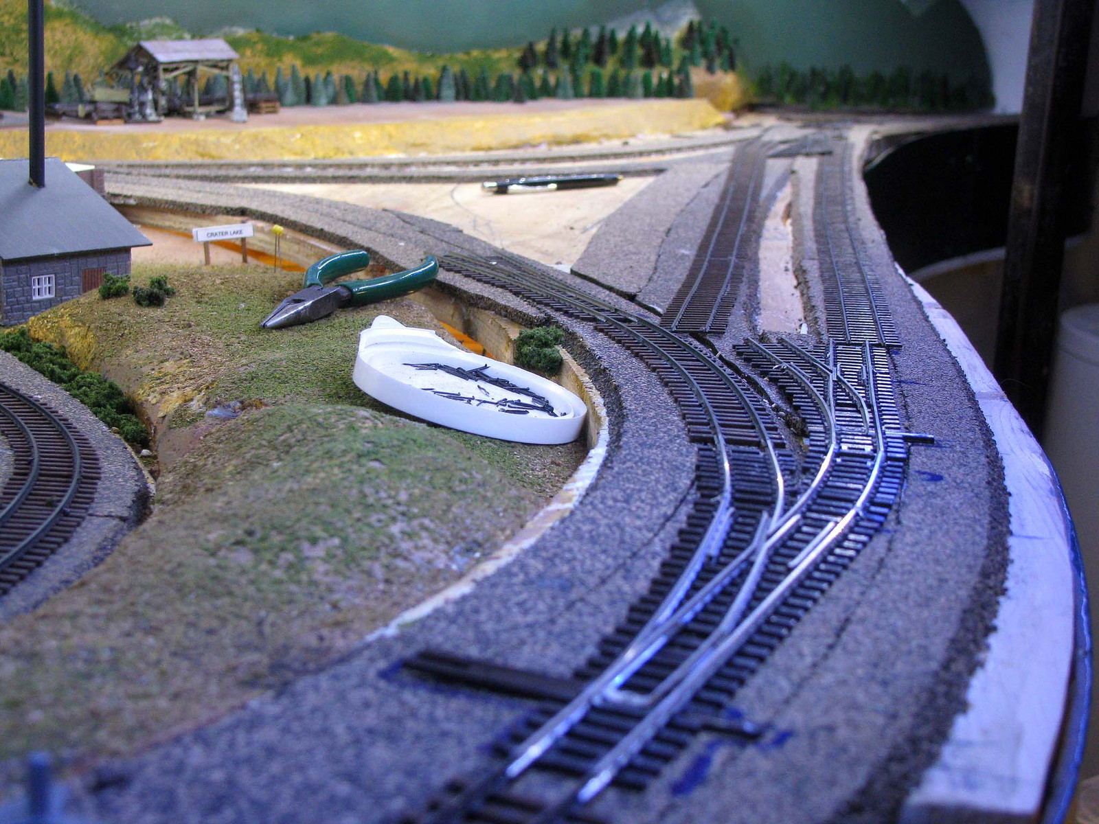
This one was sort of an in-process revision. At Crater Lake’s wye, I originally made it about as small as possible, tucking it back into the corner it sat in. Here it is roughed in, where you can see the foam on the right side which is where the fascia will be.
When I got to laying cork there, I decided the dog’s breakfast of plywood I stitched together for subroadbed should be replaced, but left the wye tucked back.
Some time passed before the finances permitted track laying, which also allowed time to reconsider things. I also needed a passing siding with the wye, so started thinking how to fit it in. And [:O], that’s a short tail track! So I decided to move the wye out some and lay a passing siding next to the fascia.
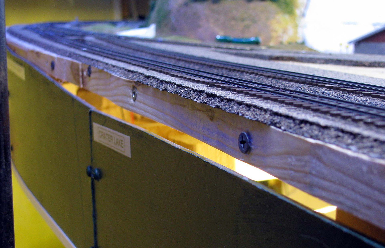
But I needed to replace the styrofoam strip here. Things just wouldn’t work well enough for the Sculptamold subroadbed trick to work for reasons I won’t bother detailing. I used cardboard templates to cut a piece of plywood to replace the foam, basiclaly a lot like the extension that started this thread, but not extending past the fascia. It was between 2" and 3" wide most of its length. Here you can see the attaching points, which I didn’t bother concealing as it’s covered by the fascia here.
The result was a more commodious wye and much better track arrangement related to it.
In regards to your plexiglass shield, I used the same technique on my layout (in process of tearing it out, to replace in a bigger room with a bigger layout, taking my time so as to be able to reuse a couple sections, like yard throat and a couple industry spurs that were already fully finished.) but for a totally different reason… We have a kitty cat. I already had a layout, with a very small buffer zone for me to operate, before we got the kitty. So, I was a little nervous of him getting onto the layout, and accidentally causing a cat-zilla style derailment, sending who knows what, down the abyss. Because of this, I had my local glass shop (who also does plexiglass safety shields for a local manufacturing plant, but specializes in window glass replacements for home and businesses for his “normal” paying jobs) create a 10 foot long “catch-fence” (to borrow the racing term) for the one long end, where the front yard tracks were about 2" in from the edge, the other edges of layout have (had) a more generous (way more generous) 5-7" buffer zone, so was unconcearned with those, and the back edge rested against a wall, so it was totally fine.
My concearn was to “catch” any knocked off/over (by Mr. Kitty Cat named Mr. Maximus Katicus, or Mr. Max for short.) from going over the edge. Instead, it turned into a “catch-fence” that “caught” my kitty… He simply tried to get on the front side of the layout instead of the two shorter sides on the sides, and never saw the plexiglass “catch-fence” along that edge.
It was a little comical to see him bash into said invisible (to him at least) fence, go running out of the room, only to return a very short time later with the (typical for a cat) look of, “Why are you laughing? I meant to do that.” on his face, with a cool, calm and collected manner about himself. (I could not help but just imagine him saying this very same statement aloud to me as he re
You do start looking at real estate along the line a bit differently once operations start. Your example is another good point about places to locate needed additions. While I see nothing wrong with in-depth planning, every plan is prefect until it’s placed into action. Then new things develop that create needs unanticipated during the planning process. I know a few folks claim they NEVER needed to do anything differently once planned, but that sounds as much like a rut as a fact to me.
Ricky,
I, too, have a barrier that works well for cats. It’s called a “door.”[;)]
Not everyone can arrange that, though, so I understand the situation. It’s good of you to take things in stride with our little feline “crew members.” I’ve got one in front of me right now making it diffficult to type.
Fortunately none of the current ones seem much inclined to walk the hidden tracks. The only time when there is access is when we have ops sessions here and the door has to stay open. So long as they stay underneath on the ground, they’re OK, but it’s havoc if they start climbing up into the benchwork…[:(]
With or without the extensions or track add-ons, when you run close to the edge plexiglass is definitely something to consider for piece of mind, rather than things in pieces.[:O]
Been meaning to update with more complete info and pics, but was engaged in yardsaling/craigslisting/ebaying most of the weekend to come up with some capital to invest in the track needed for the latest extension, plus a couple of other projects. It’s good to say that was a success[2c]
Before we start laying any track, let’s back up and go into some detail about hacking the benchwork to gain a little more ROW. I’ll note first that it’s best to have subroadbed that is 3/4" ply to make the technique I use with wood here work. The pics at the Carter Lake wye under construction do involve some 5/8" ply. 1/2" plywood would be tricky, but might not work with the fat red screws I used at Silverton, as there would be little left to prevent a screw from splitting out the edge of the plywood.
This is not an insoluble problem, though. To deal with thinner plywood subroadbed that might be prone to splitting, screw and glue an additional block of wood underneath where the screw will go into the side of it, then aim you screw to penetrate it lower.
Note I do not recommend using anything less than 3/4" for the extension itself, especially for an overhanging one. It needs to be stiff and secure to do its job, as well as providing enough material around the screws to avoid breaking or splintering out.
This is just part of the “getting ready” phase where you design the extension, verify the built terrain underneath matches your memories or plans, gather materials then lay out your cuts. You’re at the measure twice, cut once phase. Hack the fascia in the wrong spot and it could get ugly.
There are several things going on in the above pic. Obviously, the ground between the fascia is being torn out. Mine is a narrrow strip of 1" foam glued in, so comes apart fairly easy.
Less obvious are the markings in black marker. Two things are im
With the horizontal cut line marked, I used a saw blade in my knife to cut. You could use a spiral bit drywall saw, but it really throws the dust and I didn’t want that with scenery, etc around that would get “dusted.” With 1/8" masonite, the saw blade moves right along. It took maybe 15 minutes to cut.
Since the fascia is flexible with everything else stripped away, you will likely gain by holding it in one hand and cutting with the other. Also, if it’s only foam behind the fascia along where the cut is, you may be able to get away with cutting first, then remiving the foam after, which will also help support the fascia as you cut it.
Once cut, the remove the remaining foam or other scenic base between the fascia and existing subroadbed. Your cut may not be dead level, but if you’ve left a little extra and will be sanding or planing it down to fit, then those humps and bumps can be taken out by that.
I found a Stanley Surform or Hempe plane useful to leveling the cut. Keep measuring as it erodes until it’s 3/4" below the existing subroadbed. Your goal when finished is a nice surface level with the existing subroadbed. That way the fascia provide some support for the overhanging extension that makes it level with the existing subroadbed.
Note that you should also be paying close attention to swicthes, etc and their wiring so as not to damage anything. You may have to relocate them lower. In my case, they were all low enough, some just barely, to leave in the existing locations.
You saw the pic of the cut and fitted extension board laying on the lower level earlier in the thread. Here you see the nicely leveled spot it will go into.
Barely cleared the switch in the foreground[:^)]
Because of the complex curves, shaping and fitting the board took several hours and about a dozen trips to the shop before I got it fitted as nicely as I wanted. Part of the reason for this is that the edge of the existing subroadbed was not straight, but had been cut with a wandering jigsaw blade. Thus the extension board was curved on both sides.
It’s important that the subraodbed and the extension board match up pretty well or you won’t get a strong bond between them. The edges need to touch to get a good glue bond. I used TiteBond III.
The next pic is the “secret sauce” that makes this technique work, long 4.5" screws. These are made for attaching stuff to brick walls or something similar, which is why they’re red. They have a square drive, which makes them easy to drive without stripping it out.
Thing is, even these screws aren’t long enough across most of the board to penetrate deep enough into the existing subroadbed. You should have penetration there of about 1/3 the length when using longer screws or at least 1" if using shorter ones. So I used a 3/8" Forstner bit to drill a square-bottomed hole to recess the screws and let them reach deep enough to be secure. I also drilled the screw holes below that in the extension board so they had just enough room to clear.
I used short screws at either end of the board to hold the extension board in place. I installed screws and drove them just deep enough to mark where they would penetrate the existing subroadbed. Since most small diamter bits are too short to go through the extension board, I
Once the glue has set enough, then use a plane or sandpaper to achieve a smooth mating interface.
I went ahead and sketched in track locations, although they were adjusted later. This was mainly so that I could locate the cork I use accurately. Your roadbed may vary. Then I cut, glued and laid the cork.
If you did a good job of leveling, everything will mate up with the existing cork. If a small adjustment is needed, the cork can be sanded or planed to match. However, you need to be close or the vertical curve transition will be too abrupt. You want nice smooth track “close to the edge” or disaster may await[:O]
That looks pretty good, except for those holes along the edge. I bought some 3/8" furniture plugs and glued them in to fill those and provide a nice smooth surface. Then it was time for paint.
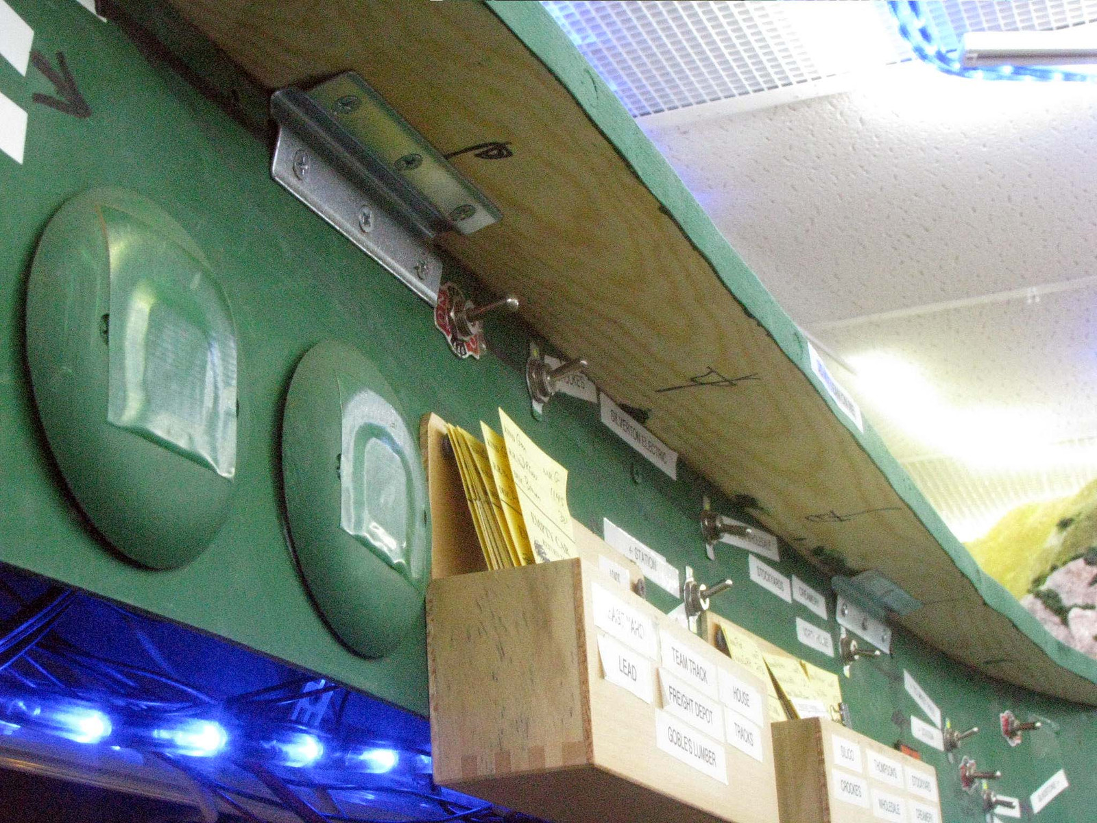
After everything was set, I still found the edge of the board was a little more flexible than I liked. The solution was to used some brackets to tie the extension to the fascia solidly, instead of just leaving it to flex by just sitting on top of the fascia. I used Stanley 4" Inside Corner Braces that installed easily and have a lower profile. Just tow of them stiffened things up nicely.[:D]
So with some cash for track, I’m ready to finish this project[swg]
I’d be happy to answer any questions. Every install will be somewhat different in details, but the technque can be widely applied with just subtle variations to adapt it to a particular location.
Track arrived and I got to work over the last couple of days in the spare time I had. I’ll post a few pics now, but hope to return with a more detailed step by step series of pics and narrative. Here’s the track laid on the extension. Nevermind the rather obvious kink, which needs a few spikes to stay put properly.
Here you can see what the extension adds to the ROW in practical terms.
The siding and spur together add about 18 to 20 car capacity, depending in car length. The 4 old yard track held 20 cars total, so it’s a significant capacity increase and will really help make ops sessions more fluid.
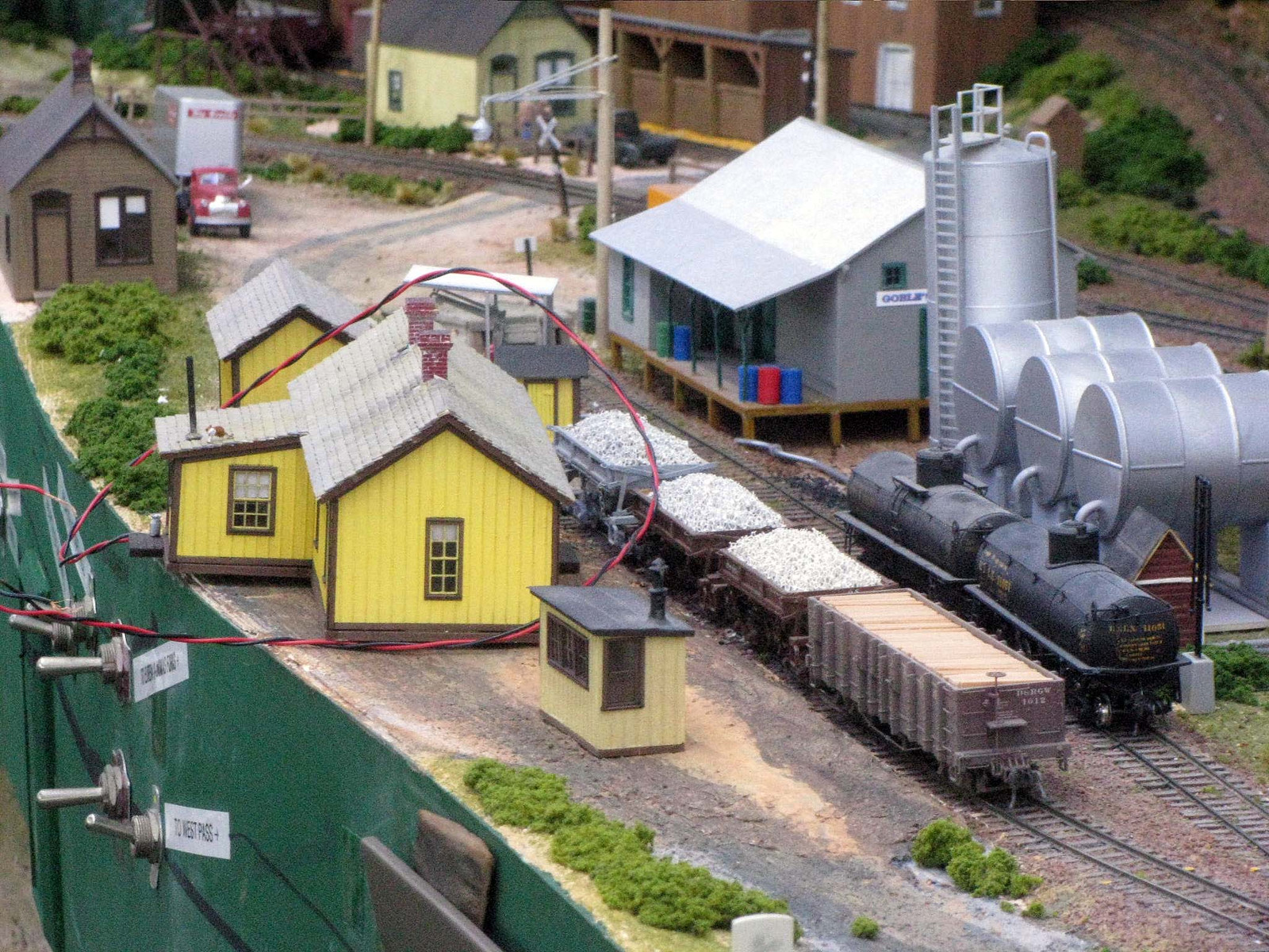
OK, let’s “backtrack” to show how I dealt with various issues in laying track on the extension. First, clear a safe zone around any major construction site. Besides moving equipment out of the way, I moved most everything, including the section foreman’s house, down to an open area and stacked it up.
Surely by this point, even if you’re like me, you’ve done some planning. Now it’s time to measure twice, so you only cut once – and do it accurately. To help with aligning the curve away from the yard lead, I needed to trim the #6 turnout to cozy it up to the existing lead. Here’s the curve, the bottommost piece of track.
The uncoupling pick denotes where the cut needs to be made.
It’s not visible, but what’s underneath counts,too. You don’t need a crossmember in the way, if possible, to make mounting the switch machine easier. I mostly am using the manual controller you can make with electrical switch boxes and 3-way switches, so I match the depth of the box to the height I have available underneath. You can also move a crossmember. The key here is to find the easy route to do it. The HOn3 rerailer from Trains, Toys, and Hobbies denotes where I found a crossmember underneath. It’s clear of the space under the points I need, so is OK.