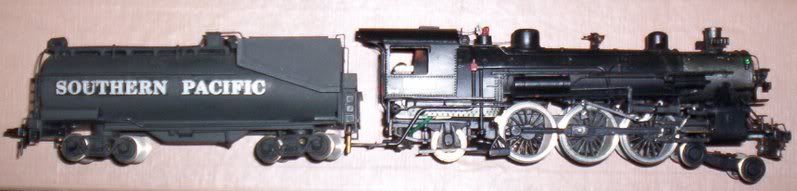
So I stumbled across what seemed like a pretty good deal on some brass pretties. In addition to some other boxes with wonderful things in them, I picked up this, my first-ever brass steam locomotive. It’s a Southern Pacific P-5 Pacific, from M.B. Austin of Hillsborough, California, and that’s about all I know about it. The detail and paint job are pretty nice, and the motor runs pretty well for an open-frame motor, it even has a lighting kit.
The thing I didn’t notice at first, because I didn’t take it out of the box, was that part of the Walschaerts valve gear on the right side of the locomotive is broken.
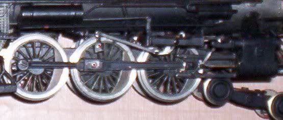
The part I think is called the eccentric is broken from the post on the driver, which means not only that the valve gear dangles off loosely, but the drive rod from the driver to the cylinder, which connects to the drive using the same post, slips off the rod in an alarming fashion. I’m sure I am mutilating some technical aspect of steam locomotive valve gear, as it isn’t really my realm of expertise.
Which brings me to my question: For those of youse familiar with the care, feeding and repair of brass locomotives, can you advise how I can fix my locomotive? It’s a beautiful thing, and even though I run electrics and diesels there is certainly room for a visiting piece of Southern Pacific steam power on my layout…if I can get it fixed!
I can’t tell you about this particular engine, but I ran into a number of brass engines where the eccentric was soldered to the crankpin. That may have been the case here. Is there evidence of solder on the eccentric?
Yup, what they said. It’s kind of a delicate operation, but it can be done with just a tad of solder and gently and quickly touching the broken part (3 o’clock with the driver in the ‘down’ position. If you’re queasy about doing it, I might reccommend the Train Doctor over at Bruce’s Trains. He’s done some repair on a couple of my brass locos and done a good job.
M.B.Austin–that’s one rare bird–probably from the late 'fifties–and worth resuscitaing, IMO. I’ve got an Austin Santa Fe 2-8-2 from that era, and with a little work, it turned out to be a nice little runner.
If you repair by soldering, it’s not that difficult. Slip a piece of paper onto the pin before soldering the eccentric in place. When you have finished tear the paper out. This will give you a bit of clearance to allow the conrods and driving rods to spin freely and more importantly protect against soldering your motion solid. I’ve assembled many brass/whitemtal kits by DJH and that is what they recommend. It has always worked well.
Actually, when the crank pin is in the 6 o’clock position, the small end of the of eccentric should be at about the 1:15 position (about 30 degrees in advance of vertical) on this engine. http://www.sdrm.org/faqs/boilers/fig68b.jpg
Edit: Oh wait a minute. I see what you mean about the small end at the 3 o’clock position. I was looking at it from a different perspective. Carry on.
Thanks!! This forum really is an amazing knowledge base. I’m confident enough with my soldering skills to give it a try using the paper-around-the-pin method. If it works I’ll have to take it to my dad’s house for a test run, as his layout has all the round-and-round loops and broad curves that mine lacks.
This engine has been out of production for years and years so finding an actual duplicate part will be a challenge. Two sources i can think of for possible substitute parts would be Greenway Products, which has a brass detail part on their website but might also have other parts not listed
The eccentric crank should face forward on both sides of the locomotive. So, if it is set at 1:00 on the right it should be at 11:00 on the left. While most locomotives have the crank set that way (leading) a few had trailing cranks. Check the left side of your engine to make sure which way the crank is set and if it is trailing then the right side should be similarly set (11:00 instead of 1:00).
If it is just a broken solder joint you seem to have a fix, just be careful you don’t solder the rods, too. If the pin is broken, they are usually just screwed into the driver, so if you carefully unscrew what is left, you should be able to match the size and threads; almost surely metric size.
I think I would consider upgrading that installation method. I would think about drilling and tapping the pin for a screw. That may not be possible but it sure is a better way of holding the eccentric in my opinion.
I’m less comfortable with my drilling & tapping ability than I am in my soldering ability.
To CAZEPHYR, twhite and bloodstainedangel: Thanks again for the advice! I tried the fix suggested and it worked–the eccentric took a little poking to solder on, but it attached nicely. A little back & forth test running and a bit of Labelle oil in the gearbox and things worked smoothly. It has some gear whine, and slow-speed operation is less than spectacular, and the valve gear does act a little funky, but it runs!
Maybe down the road a bit I’ll attempt a remotor, but for now I just added a Kadee coupler and gave it a place of honor on my 6’ of non-functional Southern Pacific mainline.
The forward leaning orientation of the eccentric is correct for engines equipped with piston valves. With slide valves, the eccentric would be toward the rear, and the points where the valve stem and radius rod connect to the combination lever would be reversed. Walschearts valve gear and slide valves were a rare combination.