I’m getting ready to start a new project for my little layout. It’s a small layout considering I’m operating O31 and Lionel Standard Gauge three rail trains, just five by seven feet and on the floor. So that configuration severely constraints my options. Eventually I hope to construct landscaped modules with at least a little bit of third dimension but I have to reverse engineer everything and build those after I make the structures.
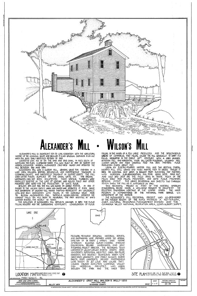
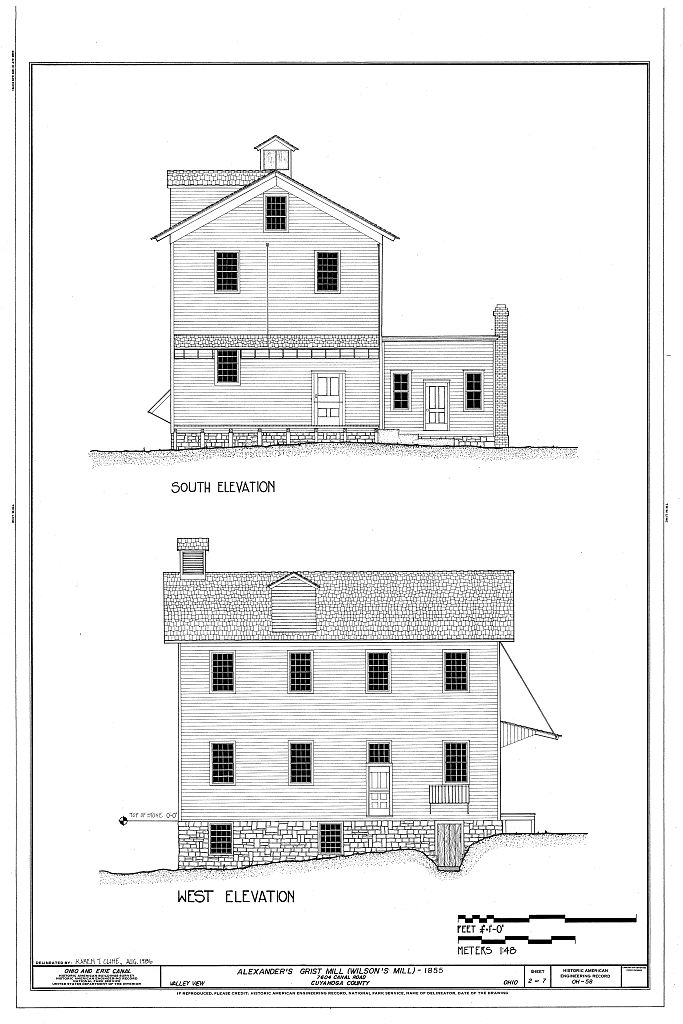
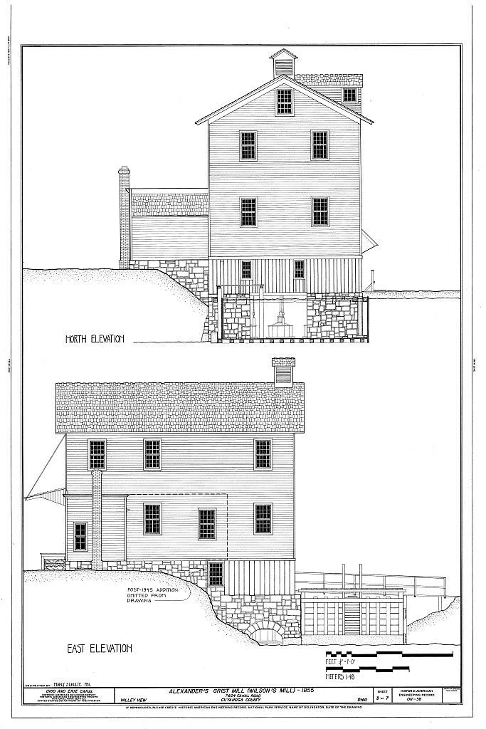
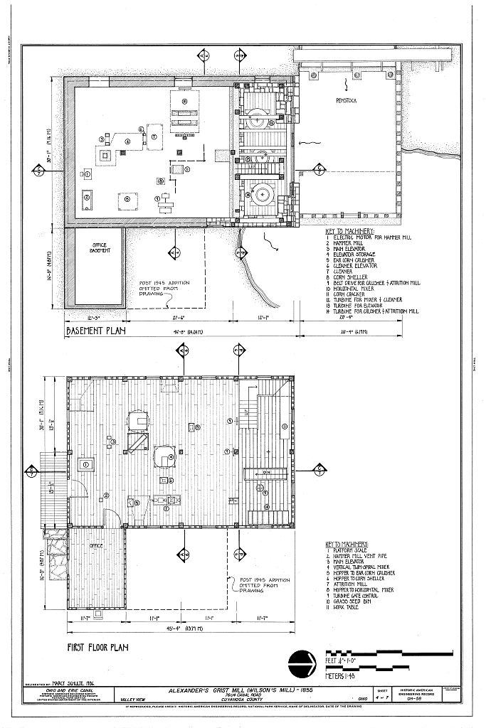
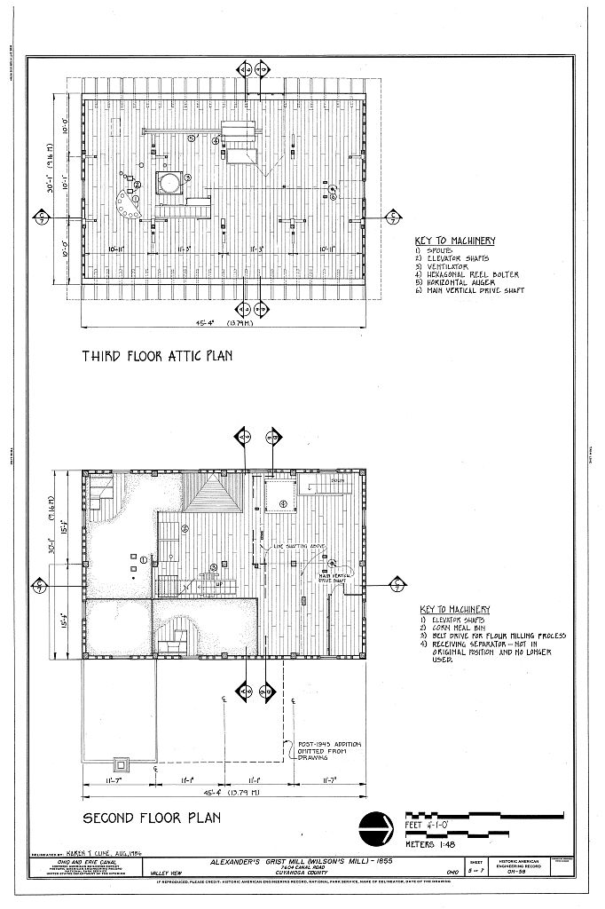
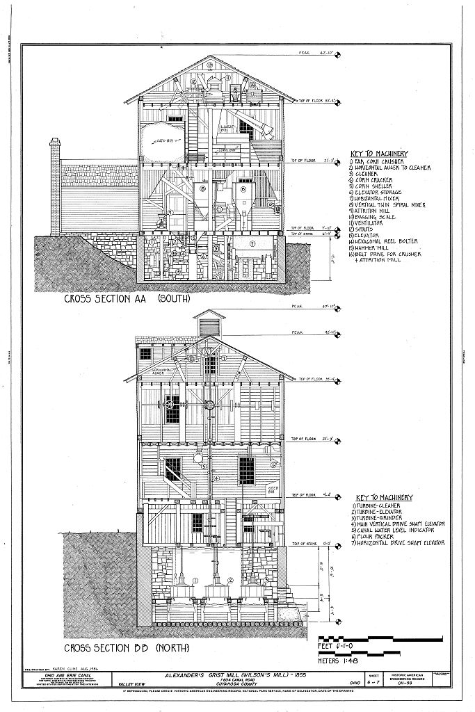
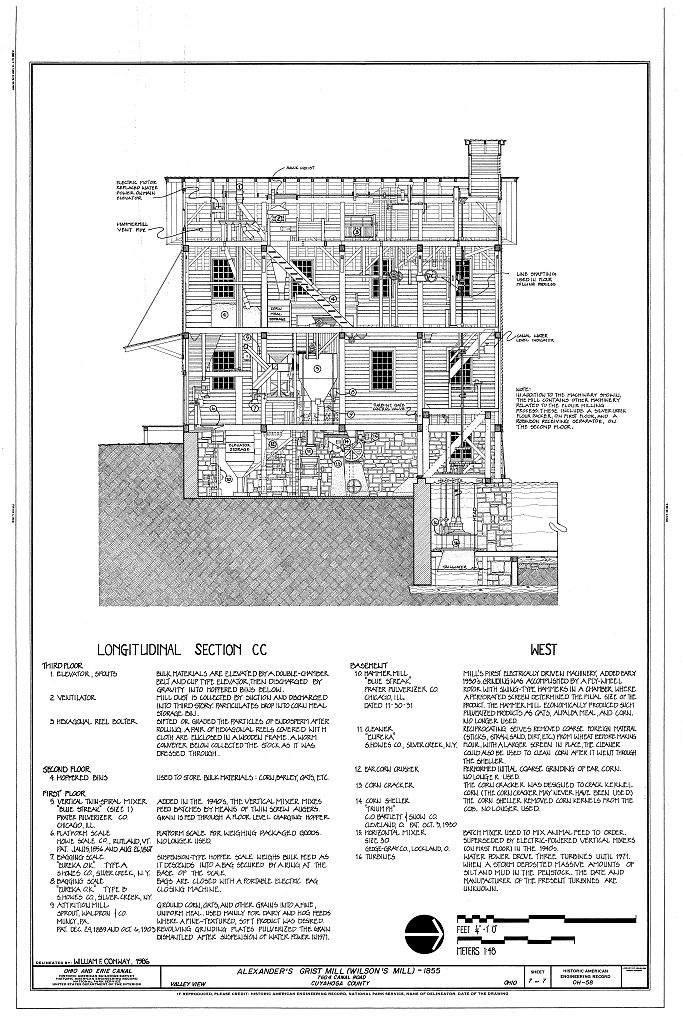
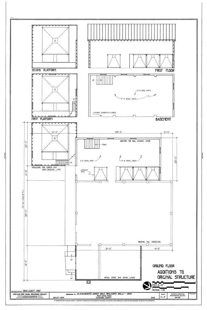
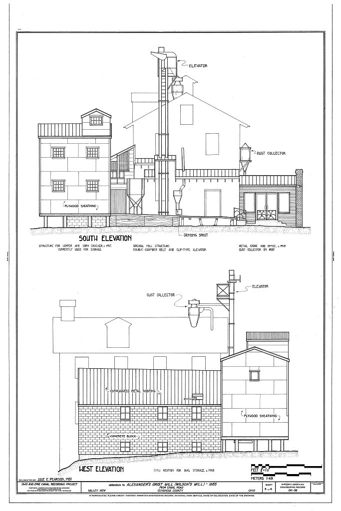
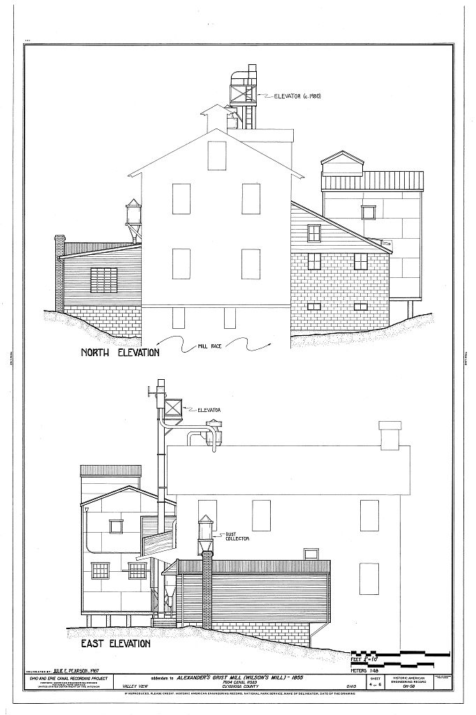
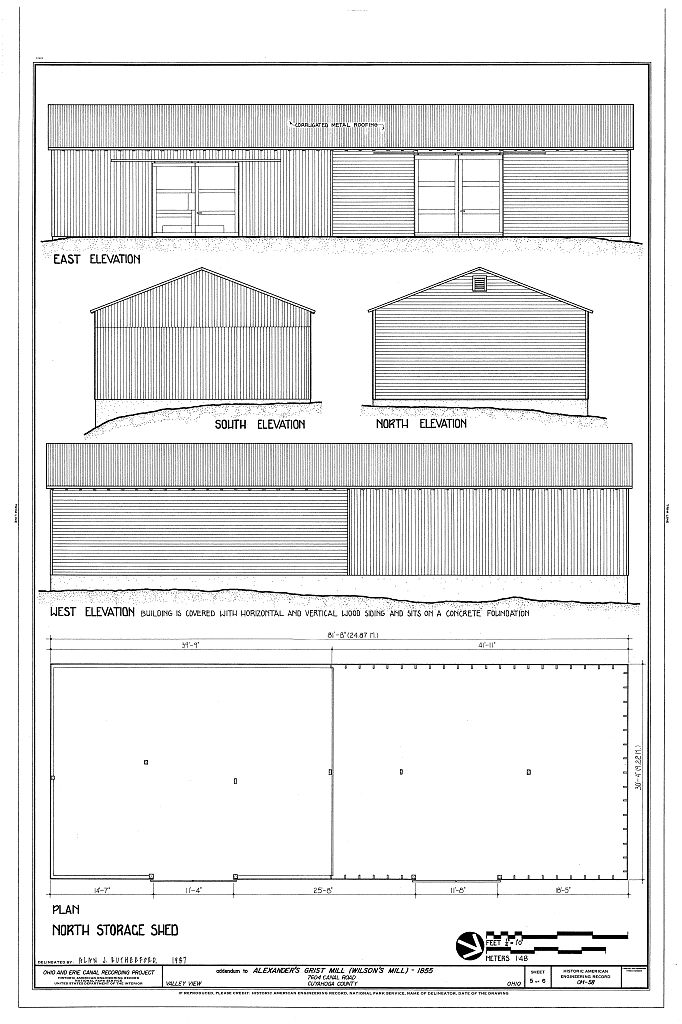
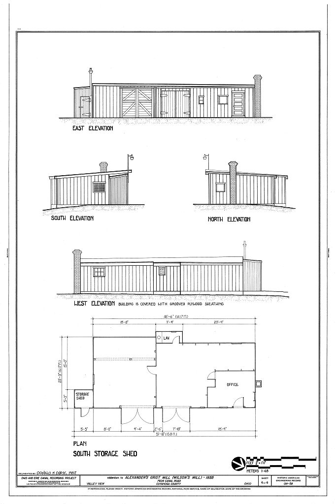
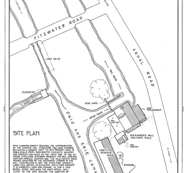
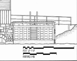
As far as the mill itself is concerned I downloaded scale drawings from the Library of Congress website.
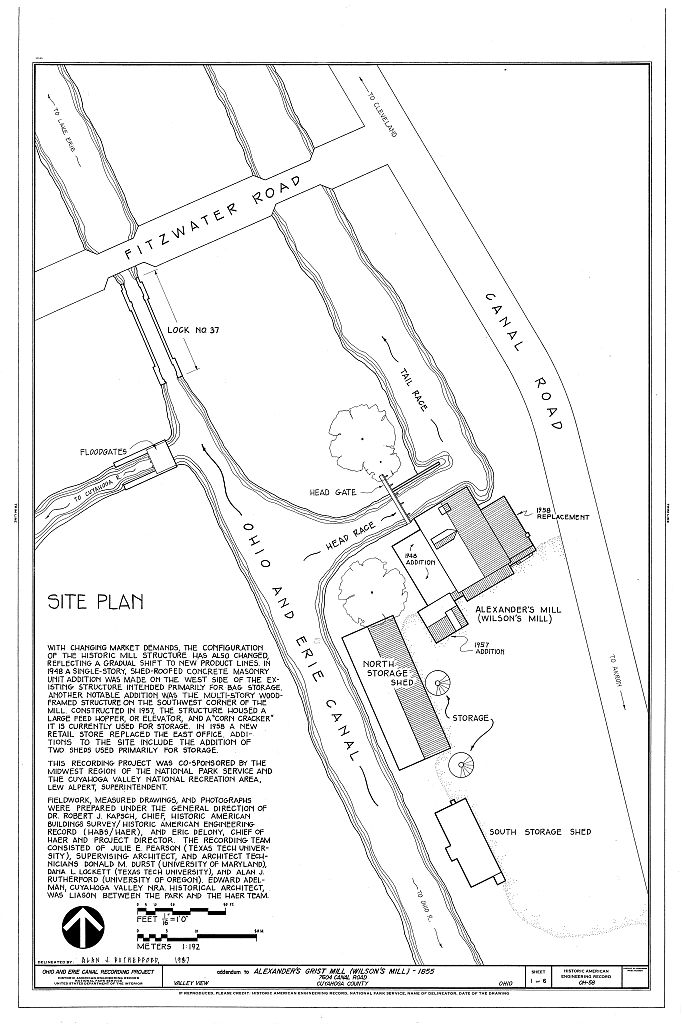
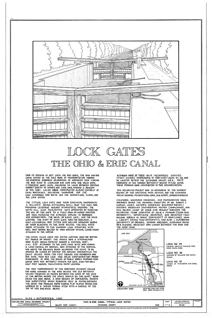
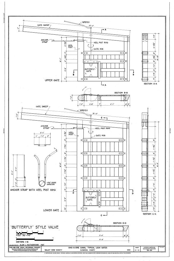
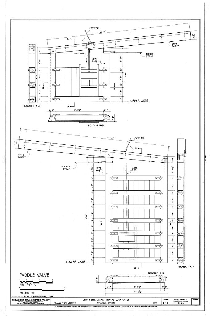
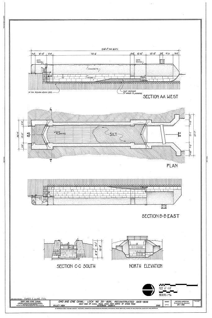
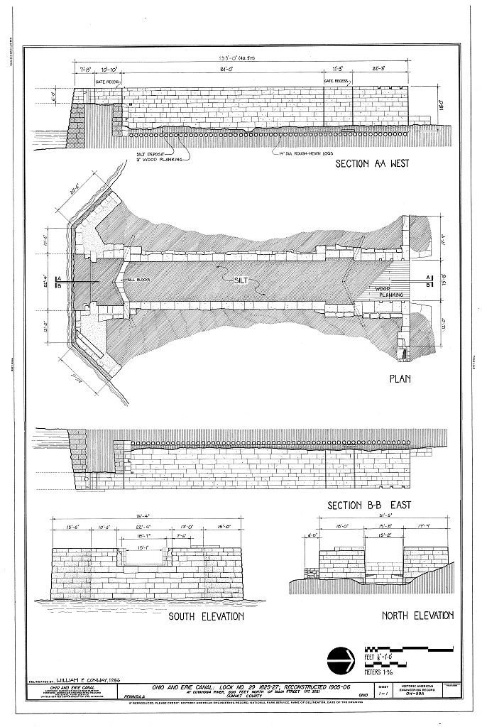
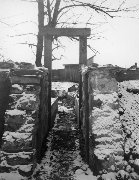
I also downloaded drawings of the kinds of locks common to the Ohio and Erie canal along which this mill is located. (It’s getting close to being two hundred years old.)
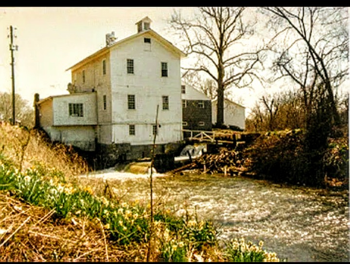
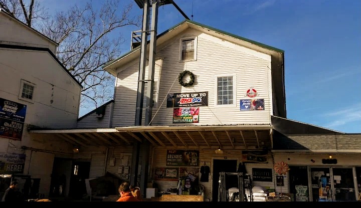
I’ve decided to try to keep my structures limited to pre 1940 because I want the layout to have a “small town railroad junction vibe”. Basically a bucolic scene of the world on the verge of massive change.
That’s what I’m attempting to build. Again, flat surface modeling will obviously complicate the construction of this type of model. The structure will be exterior only constructed almost exclusively from varying thicknesses of cardstock and illustration board. I also expect this to be a hand drawn, hand cut structure with one absolutely unchangeable requirement: no cash can be spent on the model with the exception of paint. I’ve done it before!
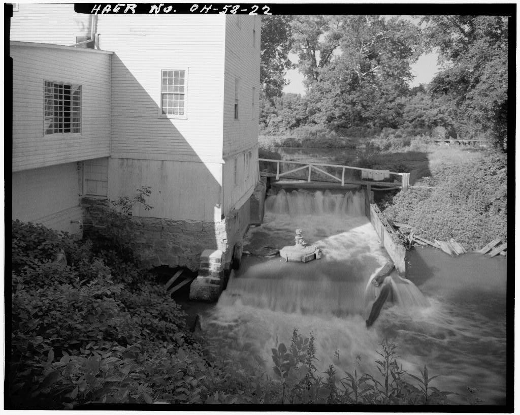
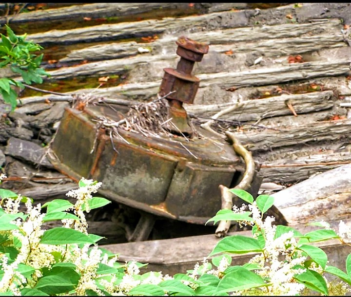
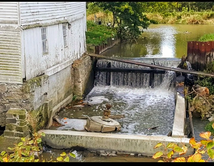
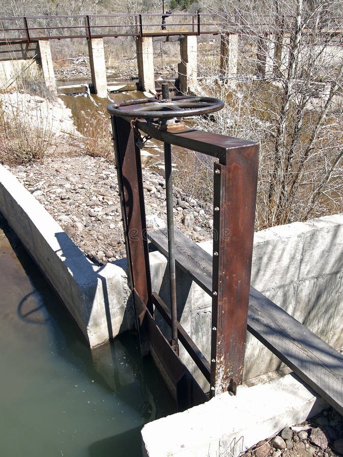
The turbine was actually inside the building when it was using water driven operation. It was later placed outside a few feet from where it was originally installed.
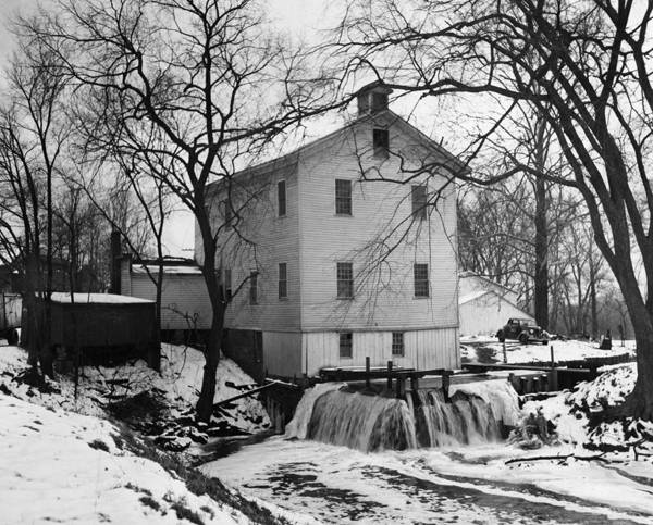
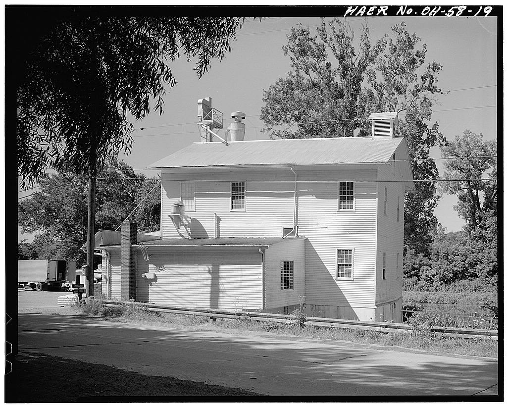
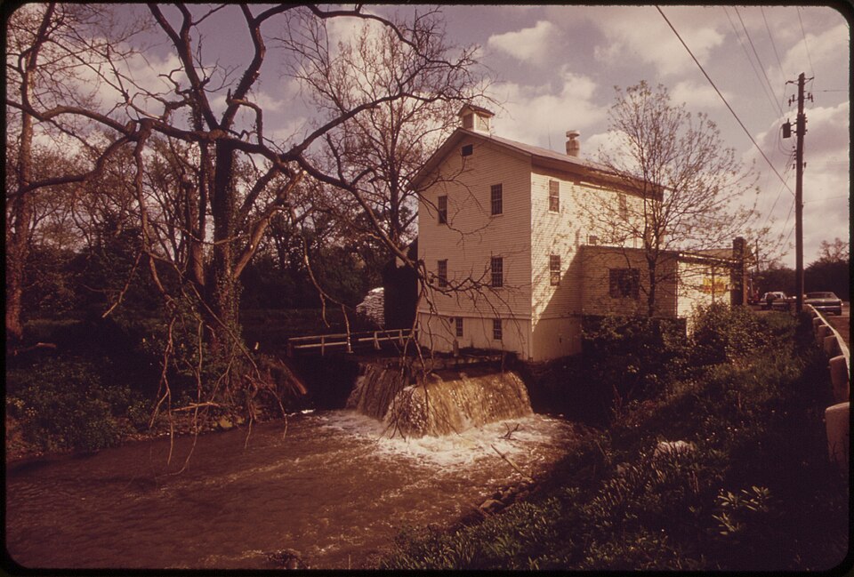
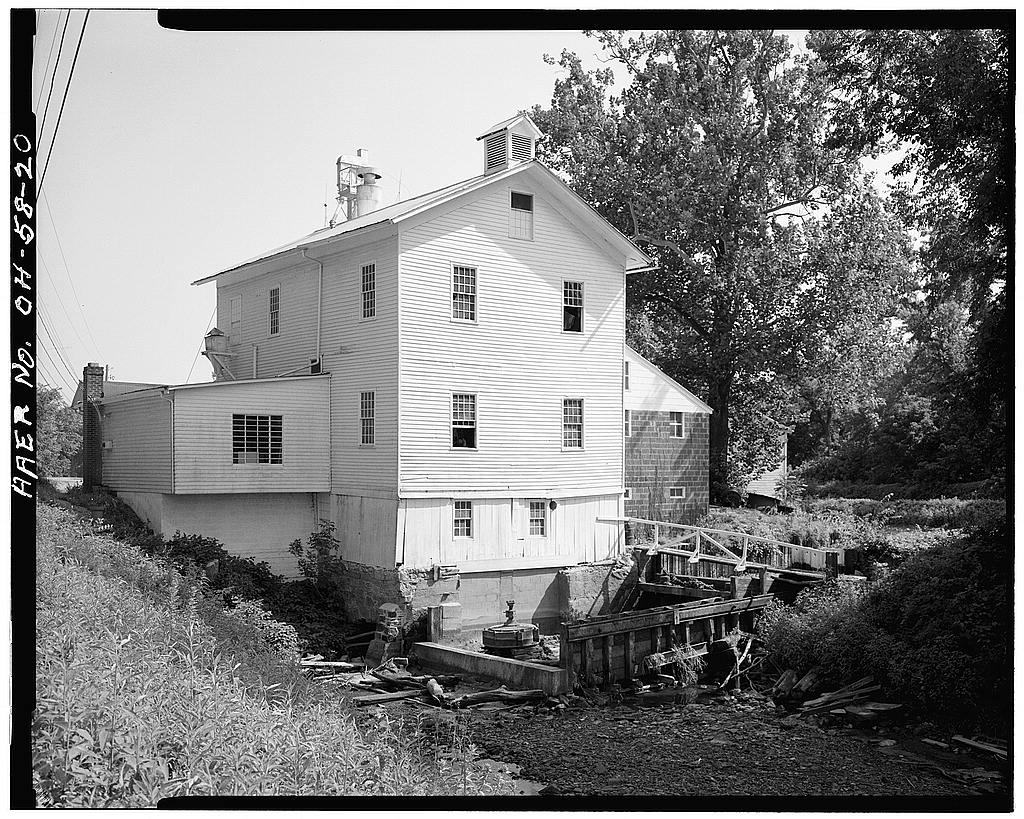
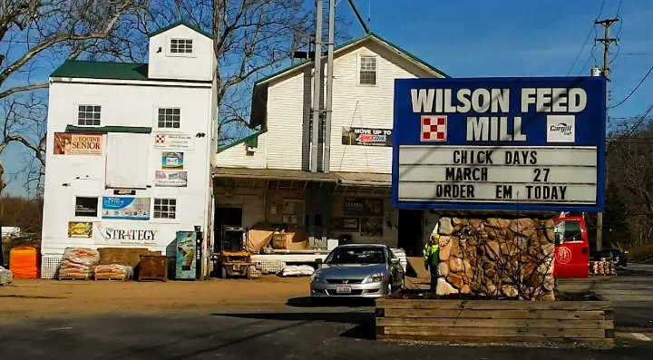
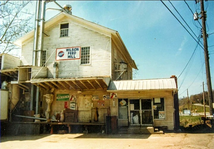
This is the mill condition I’m going to model. This is a more recent photo of the turbine from the Wilson Mills website. Yes, they’re still in business and going strong!
I should pause to mention that besides the Library of Congress and Wilson Mills websites, I located photos from the Cleveland Memory Project at Cleveland State University and any and all rights to these images remain with their respective owners.
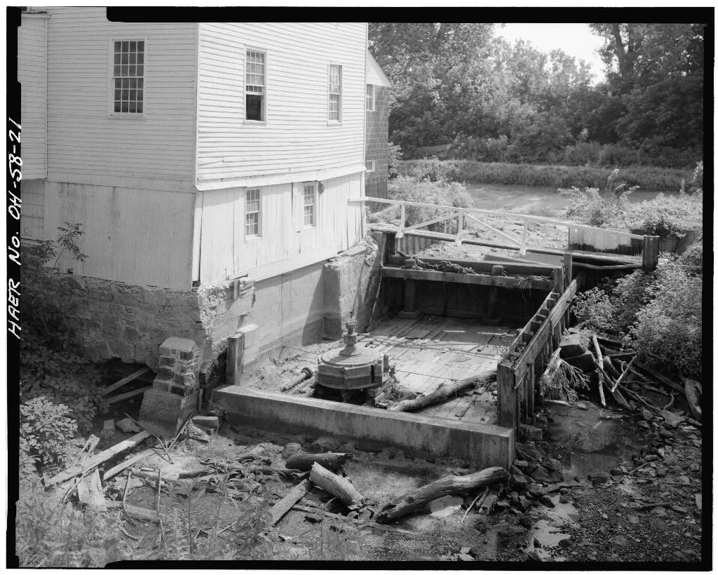
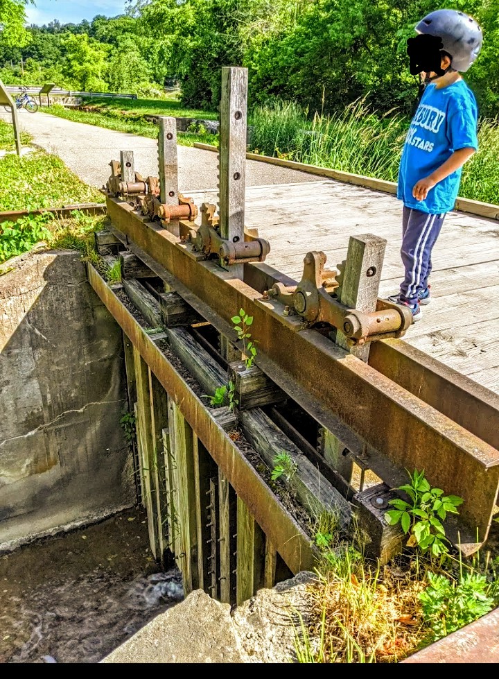
In the photos below the race was temporarily drained so the engineers who made the drawings and surveys I’m using could better evaluate the condition of the mill. I’m assuming a lot of the milled timber here was the remains of the head gate.
Any ideas? Suggestions? Wild guesses about what I should build? Any thoughts as to what the white railing looking thing over the race visible in some photos could be? Part of the gate control?
Another PS: the mill today includes additions and storage buildings I won’t be including.
This may seem like an excessive amount of effort and attention for an element that I may only be able to allot an inch and a half vertically to model. But I find it interesting. . That’s 6 foot deep in 1:48.
Many of these smaller mills, even with ‘mill ponds’, would see considerable variation in supply ‘head’ level. That implies a vertically-variable gate as part of a ‘weir’, run up and down as equipment power required.
It would be more difficult, and require stronger materials, to do that with a vertical pivoting gate, whether the forces on it were dynamically balanced or not.
An interesting Yankee innovation in the days of water power was the ‘mill clock’ used to determine employee wages. At times of low water (or as a ‘consequence’ of lower demand) the mill would operate more slowly. This would be reflected in the timekeeping of the official clock, so you’d work longer for the same ‘hours’…
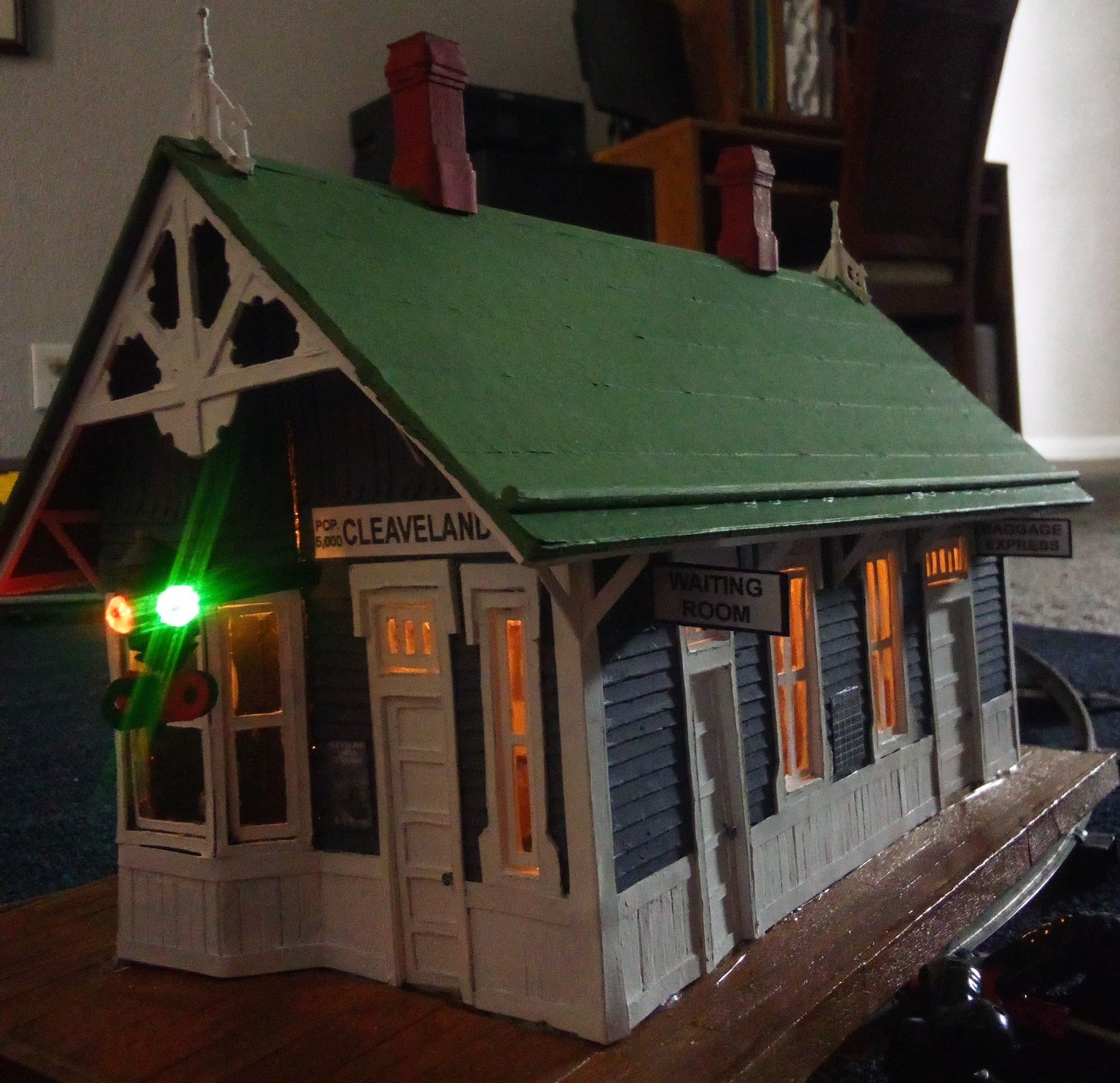
Becky, you’re a West Sider; I’m from the Heights. For the last 46 years, I have driven by Wilson’s Mill countless times on my way from Kent to “Cleaveland” (I enjoy your depot sign!) and always admire it. Thank you so much for all these photos & drawings; they give me renewed respect for the place.
I always thought Wilson’s Mill was in Gates Mills, hence Wilson Mills Road (the far east extension of Monticello Blvd). That doesn’t matter. What does matter is that your photos are awesome. Here’s hoping I’ll see you on the Towpath bike trail in the Cuyahoga Valley at the same time a CVSR train goes by.
Just curious: Do you say Cuy-a-HOG-a, or Cuy-a-HOAG-a? I maintain the former is correct as it rhymes with Geauga.
Woke: She’s from Akron, where they often get things wrong. They pronounce Cuyahoga Falls as either CAUG-a or ka-HOG-a. Either way sounds weird to Clevelanders (but hey, it’s their river, too!).
Gidday Penny, no matter what you do regarding the head gate, I’d bet you’d be wrong!
In my experience, you’ll peer at grainy photos taken from slightly the wrong angle, and after dithering for ages, will settle on a plan, built it, then someone will offer up a clear photo which shows you got it wrong!!
I hummed and hawed, (procrastinated) about what sort of davits were fitted to the Detroit Car Ferry, I was scratch building, decided that they were the more fiddly quadrantal type, made six, fitted them, only to discover a photo three years later, that they were more than likely the far simpler radial davit!!
I guess what I’m saying is, that in the absence of photographic evidence, do what you think is right, or, possibly more importantly, want to make, and have Fun.
Cheers, the idiot Bear who likes (???) the challenge of making fiddley bits!!
See, I’d tell her ‘make what would work on the prototype’ and not necessarily sweat whether that was exactly what was historically used on that particular property.
That’s anathema to most rivet counters, but it at least eliminates the improbable…
"You say ‘Cuy-a-Hogga’ and I say ‘Cuy-a-Hoaga’,
"You say ‘Ti-con-der-oga’ and I say ‘Ti-con-der-oaga’,
"Cuy-a-Hogga, Cuy-a-Hoaga,
"Ti-con-der-oga, Ti-con-der-oaga;
“Let’s call the whole thing off.”
One of the original purposes of a riding cutoff was to give ‘control’ to a locomotive using gab gear for timing and direction. One of the advantages of even straight-link (Allan) gear was the stepless control and easy reversing afforded by “Stephenson” valve gear. But fine adjustment of cutoff in the short-travel valves of the day was difficult, especially if a Johnson bar was used to move the oscillating reach rod…
Ethan Rogers of the Cuyahoga Steam Furnace Co. in Cleveland developed a riding cutoff (a mechanism that ‘rode along’ with the valve and gave fine control) that became highly favored on locomotives in the latter 1800s.
One patent showing a method of riding cutoff independent of slide-valve motion is here: