In another thred I found out that my LED’S were bad on my panel.
Am I correct that that the two Anodes will be connected together to change the LED’S from Green to Red as I throw the Switch. I can not tell on the existing panel as I have the wires covered.
Most likely not, but we would need more information on how the circuit is wired to answer with absolute certainty.
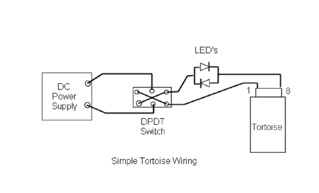
The most common way to wire LEDs and Tortoises has the LEDs wired in parallel, but opposite polarity (anode to cathode and cathode to anode). This causes the current to flow through one or the other LED depending on the direction of the curent.
Ok, in that case they should be anode to cathode and cathdoe to anode. It’s the same as Mel’s circuit above except you have the power crossed on the input to the toggle instead of the output, which makes no difference.
Anode to cathode close to the LEDs (effectively making them a big ‘bipolar LED’ if they were two separate LED devices).
As far as ‘the rest of the circuit is concerned’ there is ONE wire to a switch terminal, and ONE wire at the other side of the LEDs to the Tortoise. No ‘anode’ or ‘cathode’ is wired to anything directly, and effective polarity (which here produces direction of rotation of the Tortoise here) determines which of the two LEDs will conduct and light.
Take the LED assembly out or isolate it, and apply controlled voltage (e.g. via the button-cell field testing trick). If the assembly doesn’t light red in one direction and green in the other, you’ve turned both diodes into dark-emitting resistors… assuming the Tortoise still gets current that opens and closes it correctly. (I have never seen LEDs fail to continuity, but if they’re dark and the Tortoise runs at least one of them is conducting but not emitting…)
With the LEDs removed or bridged, measure the voltage and current in the circuit, including any transients as things start and stop. Even short overvoltage or excessive current can ruin the tiny junction that is the actual “LED” in the package.
You can fake the functionality with a pair of regular diodes with light bulbs like Mel’s recommended 1157s in series, connected at a distance to be anode-to-cathode. The light bulbs will glow ‘directionally’ and be more robust if there is overcurrent…
Make sure your LEDs work. Use a 1K resistor in series with the LED connected to your power source. If they light up normally then try one LED in series with your Tortoise. It should only light up with one polarity or one direction of movement of the Tortoise.
I have found LEDs that will conduct but not emit, its rare normally when they have been subjected to too much current they go open.
I use a single bi-color red/green two lead LEDs for my Tortoise machines.
Something that used to be common advice in the early days of LEDs was to take a battery with low nominal voltage (1.3V or under)… it can be old with voltage sagging, that’s even better… and small enough that it won’t source a lot of current without the voltage sagging. A typical small ‘button’ cell like a hearing-aid battery or ‘coin cell’ fulfills these conditions nicely. Test the LED by just connecting across the battery in the correct polarity if the rated voltage is higher than the cell’s – easy, portable, requires no meter and can be done easily in the dark or up under the layout easily.
If more modern or lower-voltage tiny LEDs or cores have come along for nominally ultra-low voltage use, you can put one of these cells in a holder with resistors on one lead, and test with that as a ‘unit’.
For those of us following this thread who are not experts on LED functionality, it sures seems like there must be a simpler way for the OP to deal with this issue.
For starters, why not just use a 2-leg bi-polar (red/green) LED instead of separate red and green LEDs?
What I do on my control panels is to attach a resistored bi-polar LED to the two center tabs on a DPDT. I have never had an LED burn out using this approach, so I am at 17 years and counting since first installing these LEDs.
Also, the OP’s initial question remains unanswered. He has 10 vdc from the power supply to both ends of the DPDT, but no power from the output side of the DPDT to the Tortoise. What is the problem?