American Flyer 3107 Resurrection

I picked this 3107 up for relatively cheap- it was originally marked for $35, but I got it down closer to $20 (in a bundle with a prewar Lionel set). She wasn’t looking too pretty, but the price was right and I thought it might just be worth taking a chance and seeing if I could save the poor thing.


Lots of issues to note here- There’s rust and paint chips pretty much everywhere you look. The wheels all have some degree of zinc pest, from relatively minor to somewhat severe. The headlight is long gone (no doubt also due to zinc pest). The insulation on the wires is falling apart. Two rivets holding the reverse unit together have popped out. One of the couplers is being held in place by a mangled piece of wire. And the tension on the pickup rollers is abysmally weak!

The plan is to avoid sinking too much money into this one, and just see how far I can get while keeping things mostly original.

I have lots more pictures to post, stay tuned!

-El

8 Likes

First steps…

Like with any project, the only way to begin is to begin! And in the beginning, most repair projects start with disassembly. In the case of this model, the only particularly feasible way to work on the motor is to remove it from the frame. It is held there by means of two cotter pins- however, the cotter pins cannot be removed without taking the shell off first!

The shell is held down to the frame by 4 tabs. The paint was chipped off of all 4- could someone have been in here before me? Hard to say.


I did my best to capture several angles. As you can see, everything was quite filthy, and as tends to be the case, the insulation on the wires was dry as a bone and it crumbled to pieces when disturbed.
The front end (note black wire for headlight):

The back end (with manual reverse switch):

From the top:

Some 3/4 views:


With the shell off, it was fairly straightforward to remove the cotter pins and work the motor out of the chassis. Unfortuntely, the paper insulator for the brush plate did not survive this procedure.


Next up… motor overhaul! Stay tuned…

-El

5 Likes

Nice going Ellie! Aside from the bum wires it looks like it’s still pretty much all there.
Oh, and did you get the package?

2 Likes

Yes, indeed. We’re down a headlight, but I should be able to pick up a repro without trouble. Otherwise all the bits are there.

Sure did :+1: looking forwards to testing it out :grin: tysm!

-El

1 Like

Outstanding!

1 Like

Motor? I hardly know 'er
I mean- er, that is…

Motor repair! We’re doing motor repair in this one :grin:

As seen in the last post, I successfully separated the motor from the body and the frame.


I have to say, the motor was every bit as filthy as the body! Old, hard grease and oil all over the place.

To begin, I disconnected the wires from the brush plate. Because of Flyer’s design, they must be removed very carefully so you can prevent the brush springs and their little ‘end caps’ from flying into the stratosphere as soon as the wires are slipped out of the brush tubes.


With the wires disconnected, I removed the brush plate next. Two screws hold it in place. Note the brushes were neatly left behind- no, this was not staged!

with the brushes out of the way, we can see better the state of the commutator. It’s not all that bad, a bit grimy but I’ve seen plenty worse on models with fewer years behind them.

The armature needed to be rotated so that it would clear the ‘nub’ at the bottom of the opening in the side plate, and then it pulled straight out with no fuss. I did not find any washers/shims on either end of the shaft.

Unfortunately, I neglected to snap pictures specifically of the brush plate or rear armature bearing plate. The brass ‘pocket’ pieces on each were loaded up with old, hardened grease. I had to soften it with oil so that it could be scraped out easier.

After the armature was out, I set about removing the manual reverse switch. It looks suspiciously like someone attempted to remove it in the past, and mangled the side plates of the motor in the process:

I had no real issues getting the switch out. Two of the 4 rivets that hold it together had already been ‘popped’, I took care of the remaining 2 and pulled it apart for cleaning and lubrication. Here you can see all the pieces laid out:


Simple but effective, and quite sturdily built!

The next piece to tackle was the pickup rollers. The the rollers were dirty, the tension on them was very weak, the fiberboard insulator was cracked, and the wires running up from it needed new insulation. To give myself the room to spread the motor plates, I first pulled the wheels:


Then, after a few minutes of careful prying, I got the roller assembly out:

The use of a Fahnestock clip to connect the wires is interesting to me, as most collectors I’ve seen are soldered. I don’t know why Flyer used the clip, as it’s really tough to reach down in there when the motor is assembled. I just don’t see how it provides much advantage over a solder joint, which would (in theory) be cheaper. Note the two wires. The black wire goes to the headlight, the bare (formerly white) wire goes to the motor field.

I love manufacturer badges on collector assemblies, especially old ones like these with the embossed lettering and black background. They’re kinda stylish, no?

I spent a while cleaning up the collector assembly, as well as working hard to try and soften old grease and clean it up from the motor plates. It took quite a while, but I think the results were worth all the fussing:


That’s all for now! In the next post, we’ll talk wheels, specifically how I was able to salvage the original set! Stay tuned.

-El

6 Likes

Fantastic! Like watching a crack surgeon at work!

1 Like

Defeating the Pest
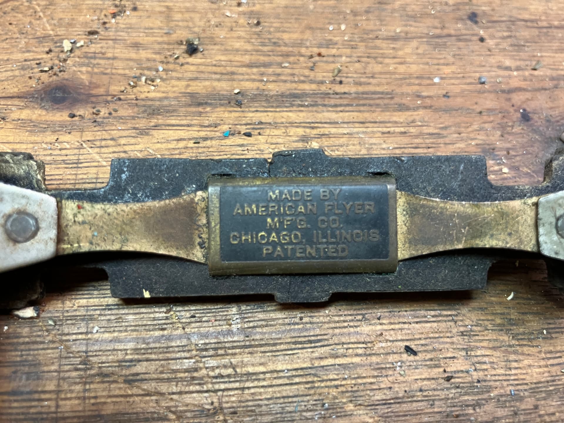
One of the biggest uncertainties with this project was the wheels. As was the case for many locomotives of the 1920s and 1930s, Flyer used diecasting to create the wheels for the 3107.

As I understand it, diecast metal was a relatively new, developing technology for manufacturing. There were many advantages- unlike other forms of metal casting, you could produce thousands of parts from the same mold. The metal alloy was relatively cheap, and highly detailed castings could be produced in large volumes. It’s no wonder that it was quickly adopted by manfuacturers of toys and models.

But there was an unforeseen problem- many early castings would mysteriously deteriorate over time- cracks would appear as the metal warped and expanded, turning brittle in the process. This disease goes by a number of names, but I most commonly see Zinc Rot or Zinc Pest used to describe it. Toy Train collectors know this phenomenon well, as it has affected the vast majority of trains produced through the 1920s and 1930s that had diecast metal parts. Generally the explanation is that it is caused by “impurities in the metal”. But one thing I haven’t seen widely explained and understood is why it occurs.

Zinc is generally the primary ingredient of diecasting alloys. Like any other metal, comes from the earth. Deposits are located, mining operations extract the ore, and then the Ore is refined into metal that can be used to manufacture goods. However, for reasons I am not privy to, Lead deposits often turn up around deposits of Zinc. It seems pretty likely that this is the most common way that lead ends up in the diecast metal in the first place.

The other piece of the puzzle is, why does the presence of lead cause the issue? What exactly is going on? A year or two ago, reading a forum somewhere lead me to a research paper that provides a satisfactory explanation of what is going on. You can read the paper here: Corrosion-induced cracking of model train zincaluminium die castings
While I cannot parse the discussion of metallurgy the best, I understand the explanation the paper lays out on what zinc pest is/how it works, and will summarize it as best I can:
Metals have a crystalline structure- this structure is an important piece of how zinc pest causes havoc. Depending on how rapidly the Zinc Alloy is cooled from its liquid state, the size of the crystals will vary- a more rapid cooling generally results in smaller crystals. Smaller crystal size results in a greater number of intercrystalline boundaries.
Zinc Pest is caused by corrosion, which occurs in the presence of moisture, and is accelerated by heat. Impurities, such as Lead, Tin, and Cadmium result in very severe corrosion of the metal. Due to different melting points and how the metals interract with eachother, these impurities will generally wind up along intercrystaline boundaries.

The result is that, as moisture reaches impurities, they will corrode- the byproducts of this corrosion force metal apart, along intercrystaline boundaries, resulting in the cracks and warpage of the metal. As metal cracks apart, moisture is able to reach in further- the process starts from the outside and works its way in.

So, that’s the low-down on why Zinc Pest happens. If anyone thinks either me or the paper’s authors made a mistake, please let me know!

This does leave us with a question though- what do you do if you have a set of zinc pest damaged wheels? The most sane, applicable answer is to buy reproductions. A full set of reproduction wheels to fit my 3107 can be had for anywhere in the $40-50 range as of this writing.

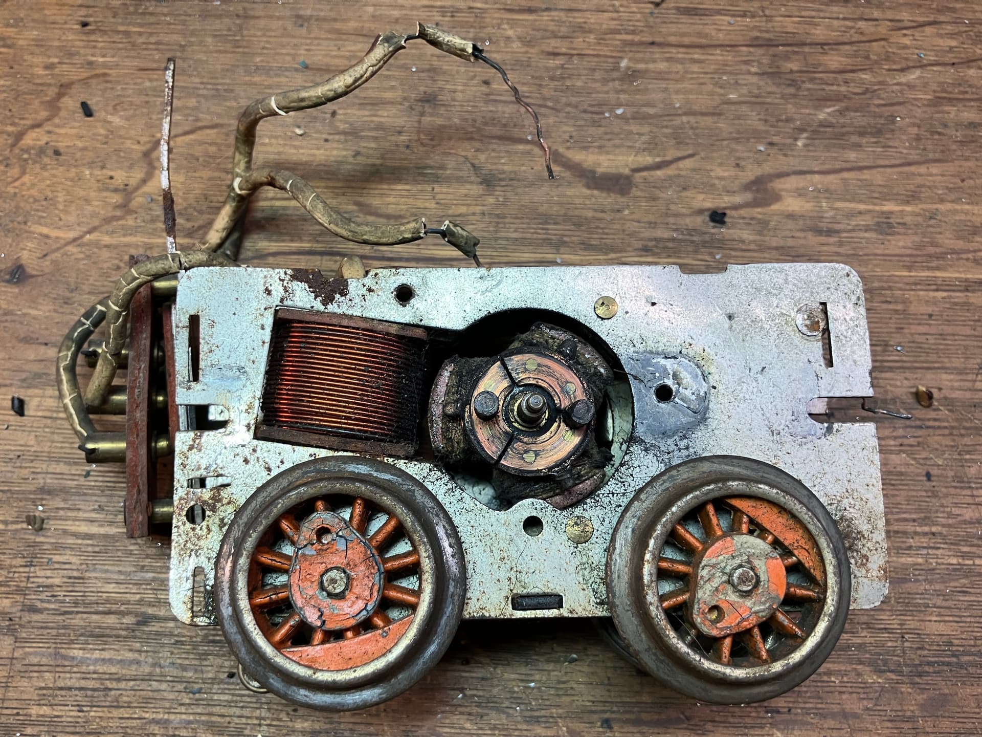
Knowing this was always an option, I decided to try a different approach before I went ahead and bought replacements. As can be seen in prior posts, the wheels are generally holding their shape, and the actual wheel thread and flange are made out of a steel rim which has not deformed.

I decided to attempt to clean up the wheels, and use thin CA to fill cracks and help provide a little strength where the metal had been weakened. The hope was that this would be enough, but it didn’t take long to realize that swelling of the wheels had thrown the gauge way out of whack.

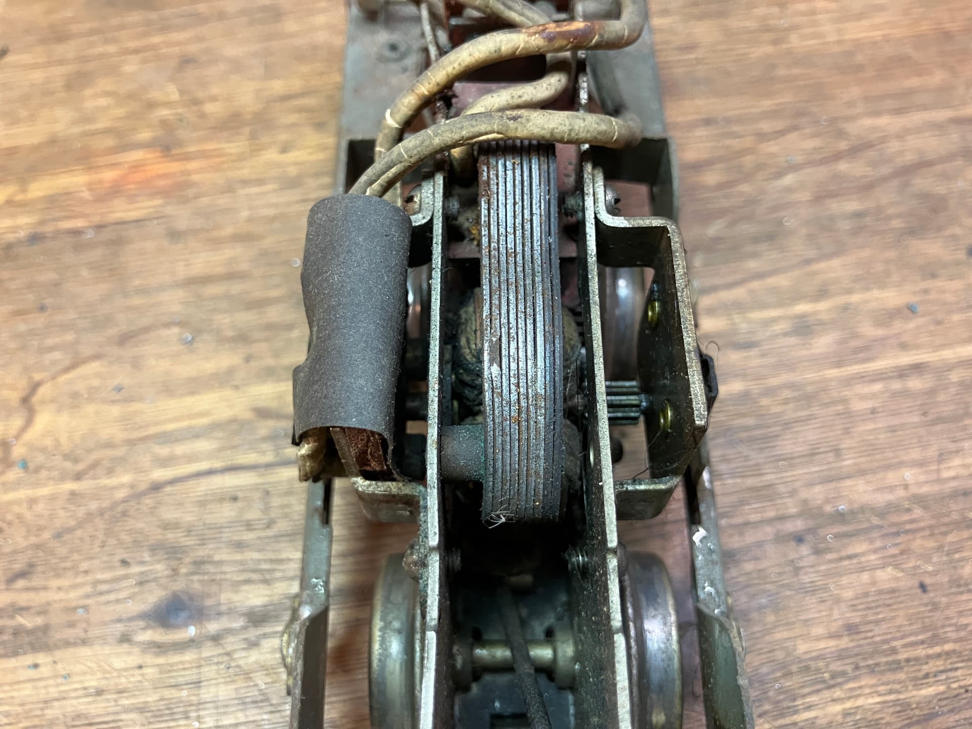
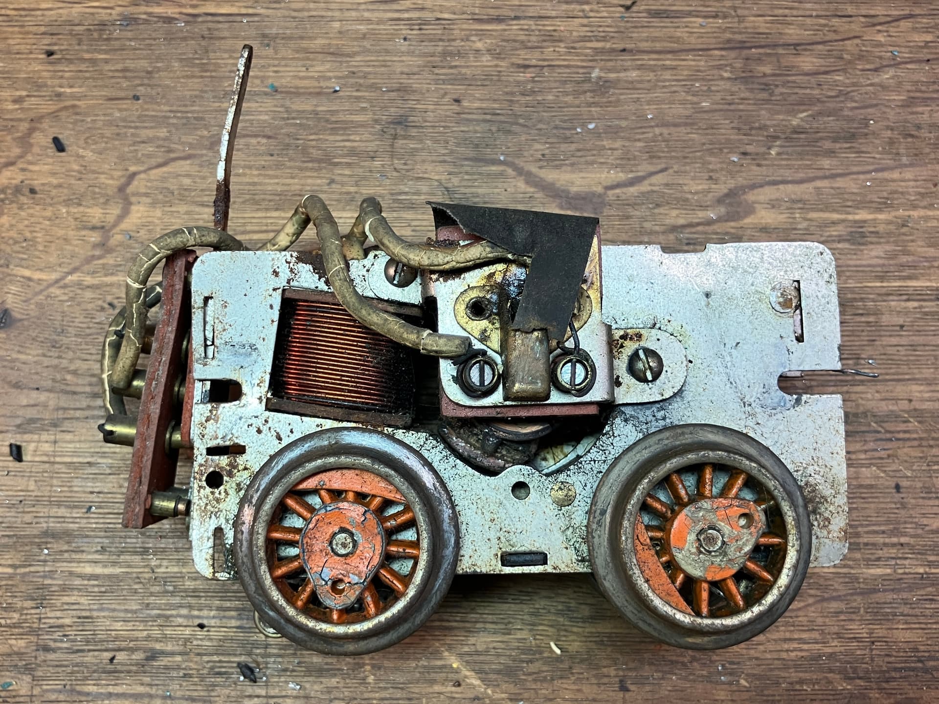
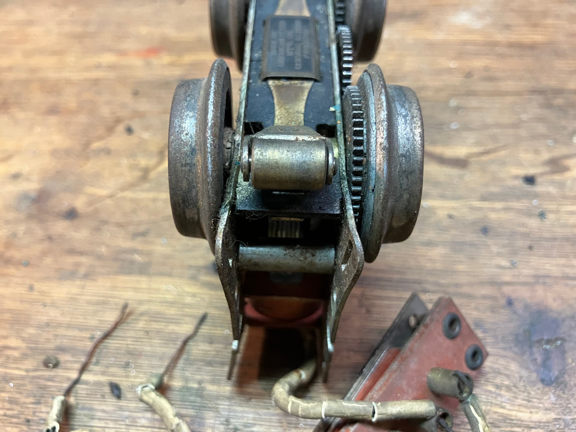
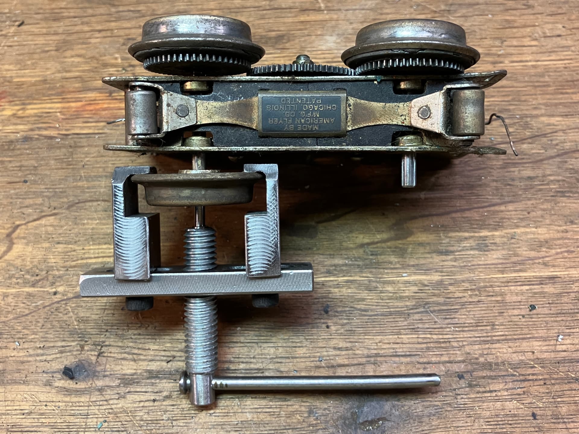
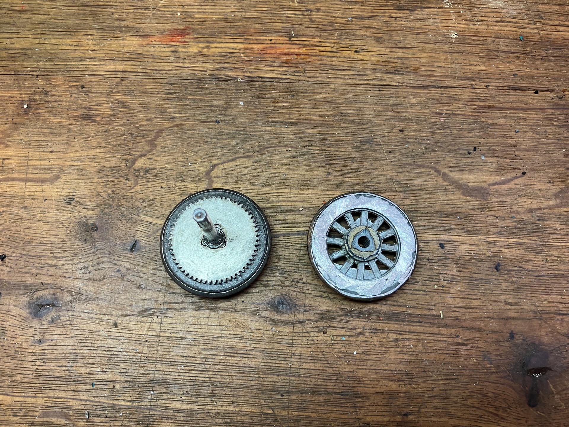
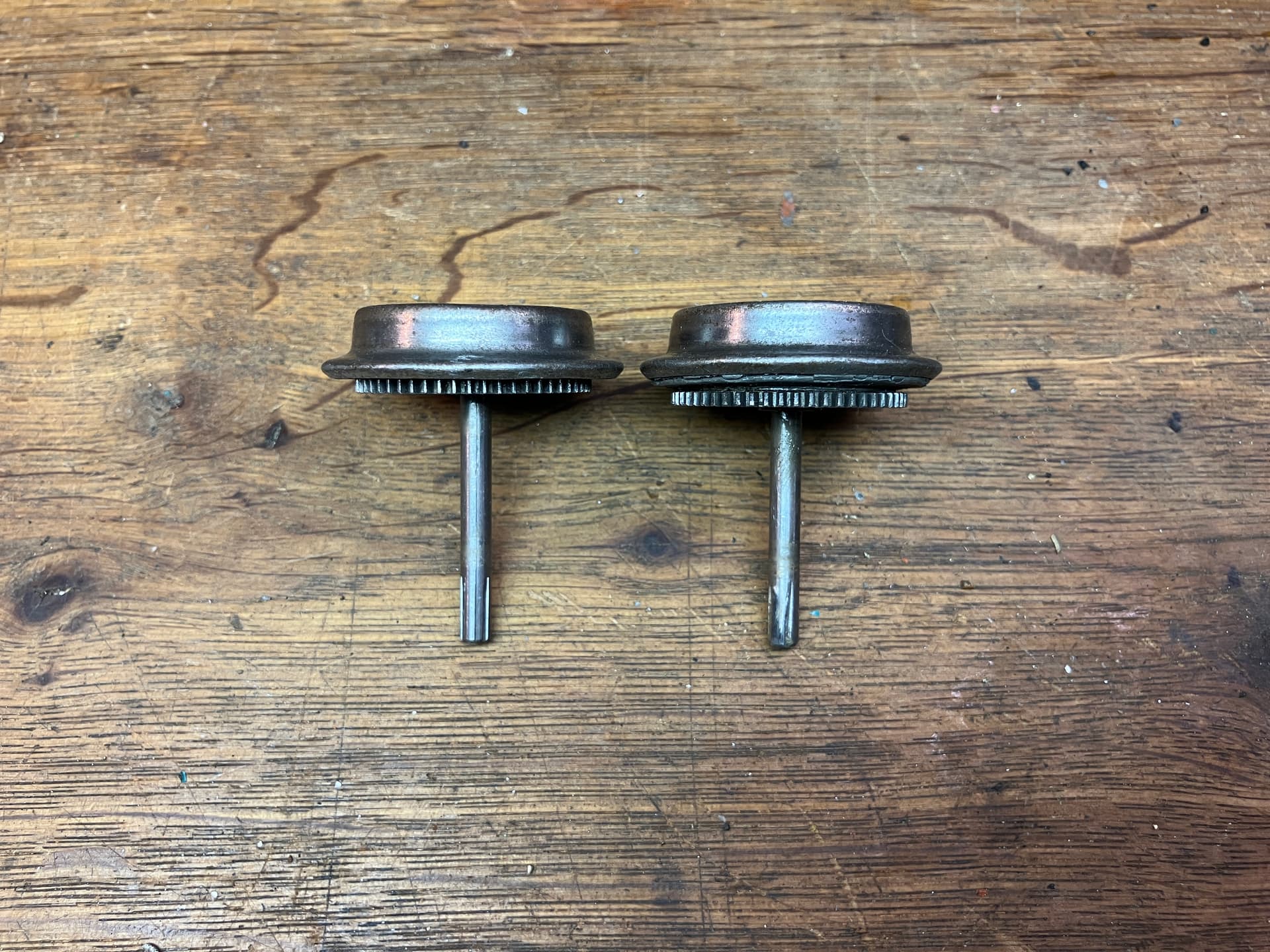
The worst swelling appeared to be entirely limited to the gear wheels. What I ended up doing was prying off the gears, and grinding away metal from the backs of the wheels until the gears could sit flat against the backs of the wheels. Then I put things back together to see if they would work. Here are some pictures, showing an un-altered original wheel and axle on the left, and a ‘rehabilitated’ wheel on the right.


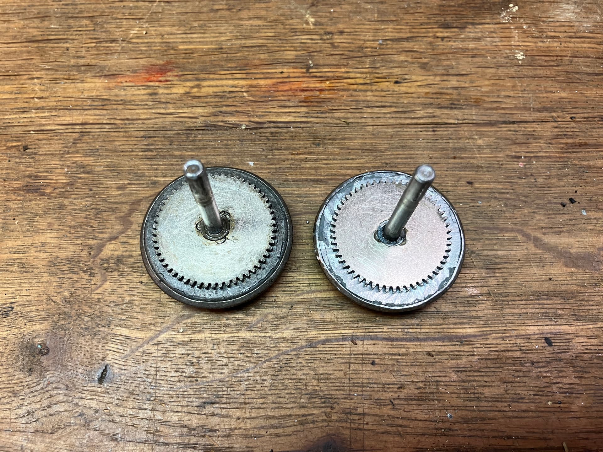
And here is another picture, this time with the rehabbed wheel on the left and the original one on the right, to illustrate just how far the swelling had spread out the gear and wheel flange:

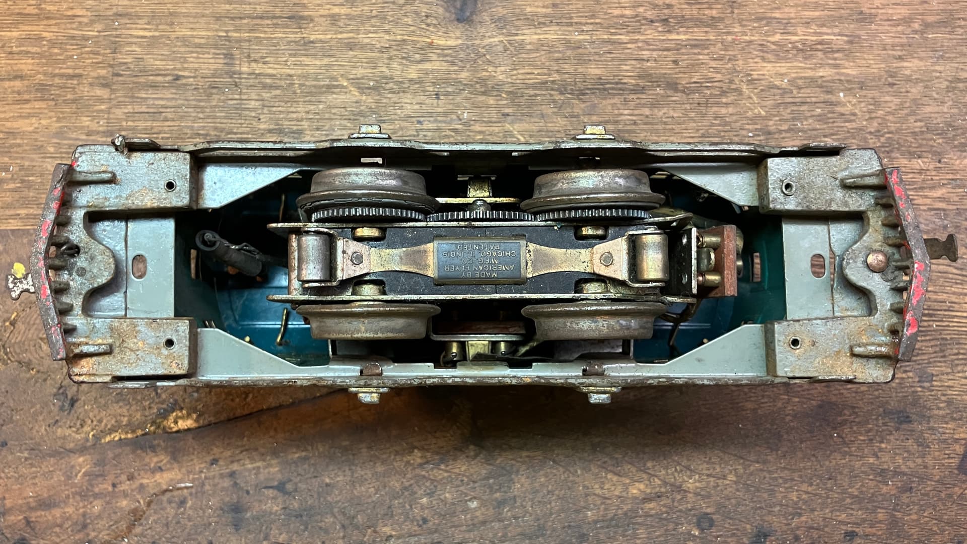
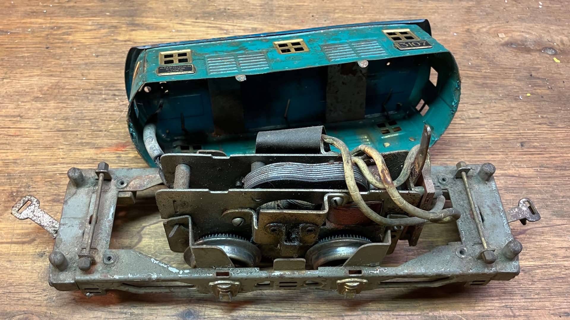
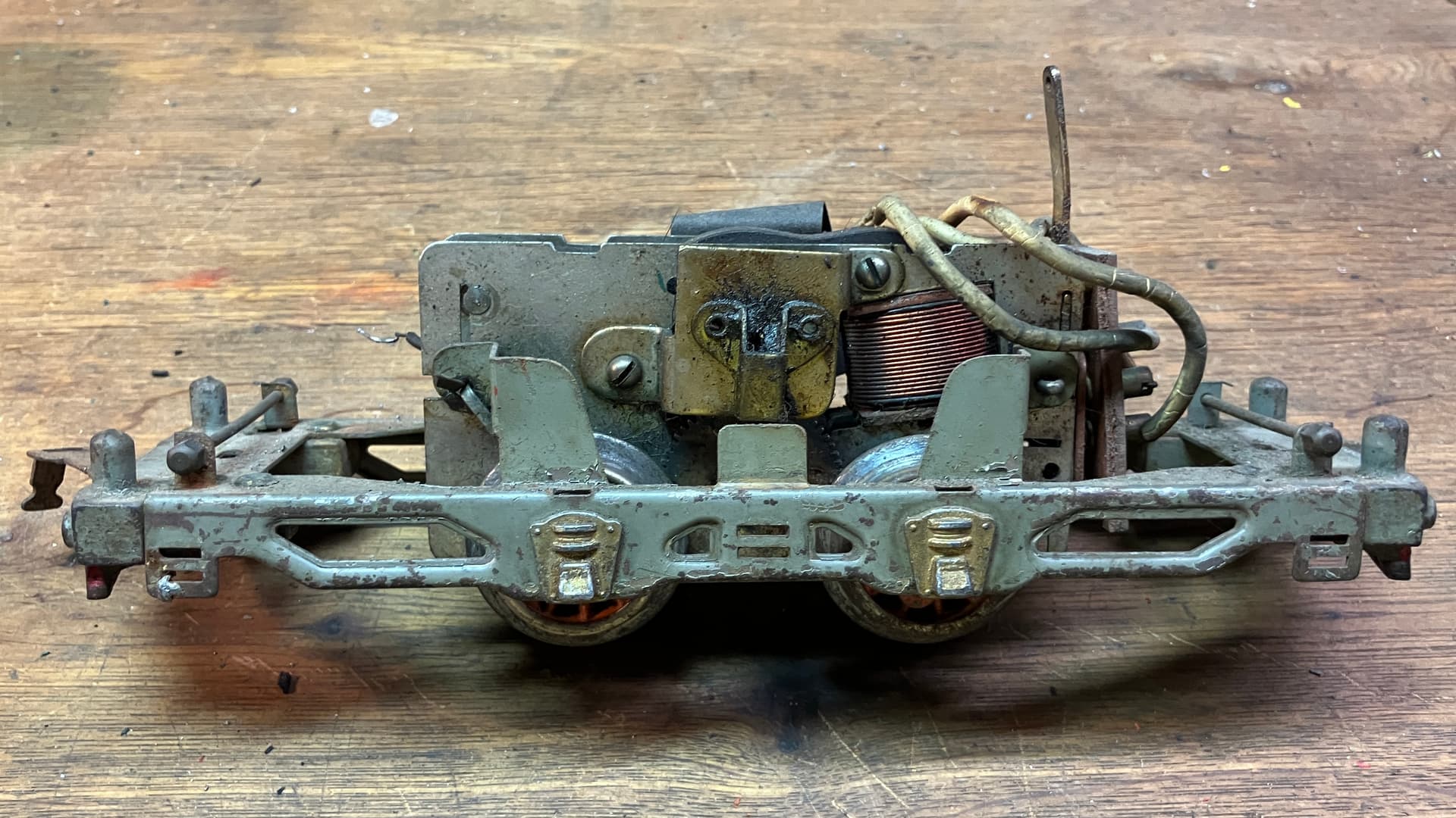
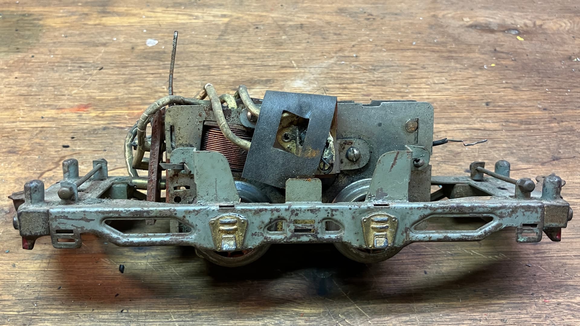
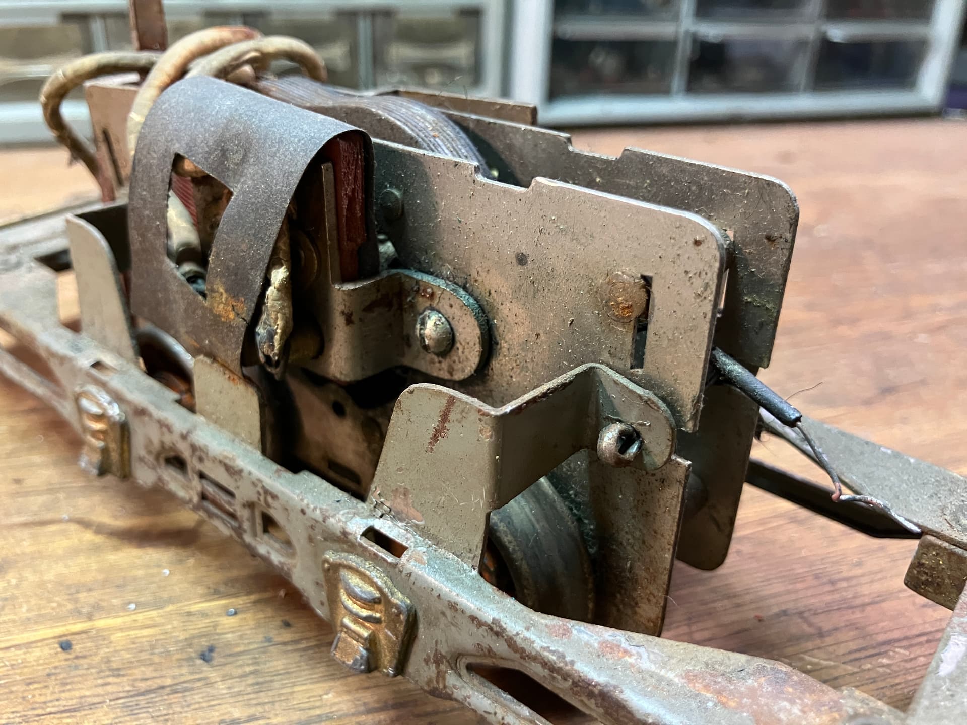
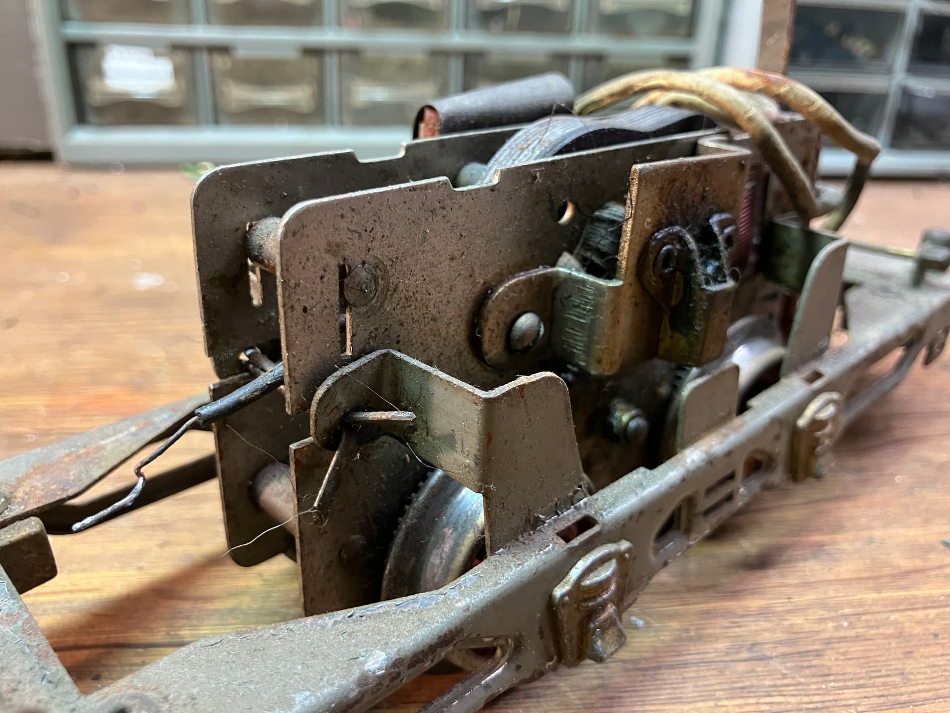
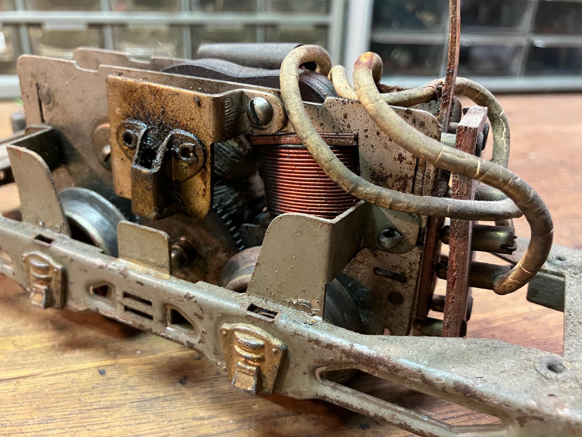
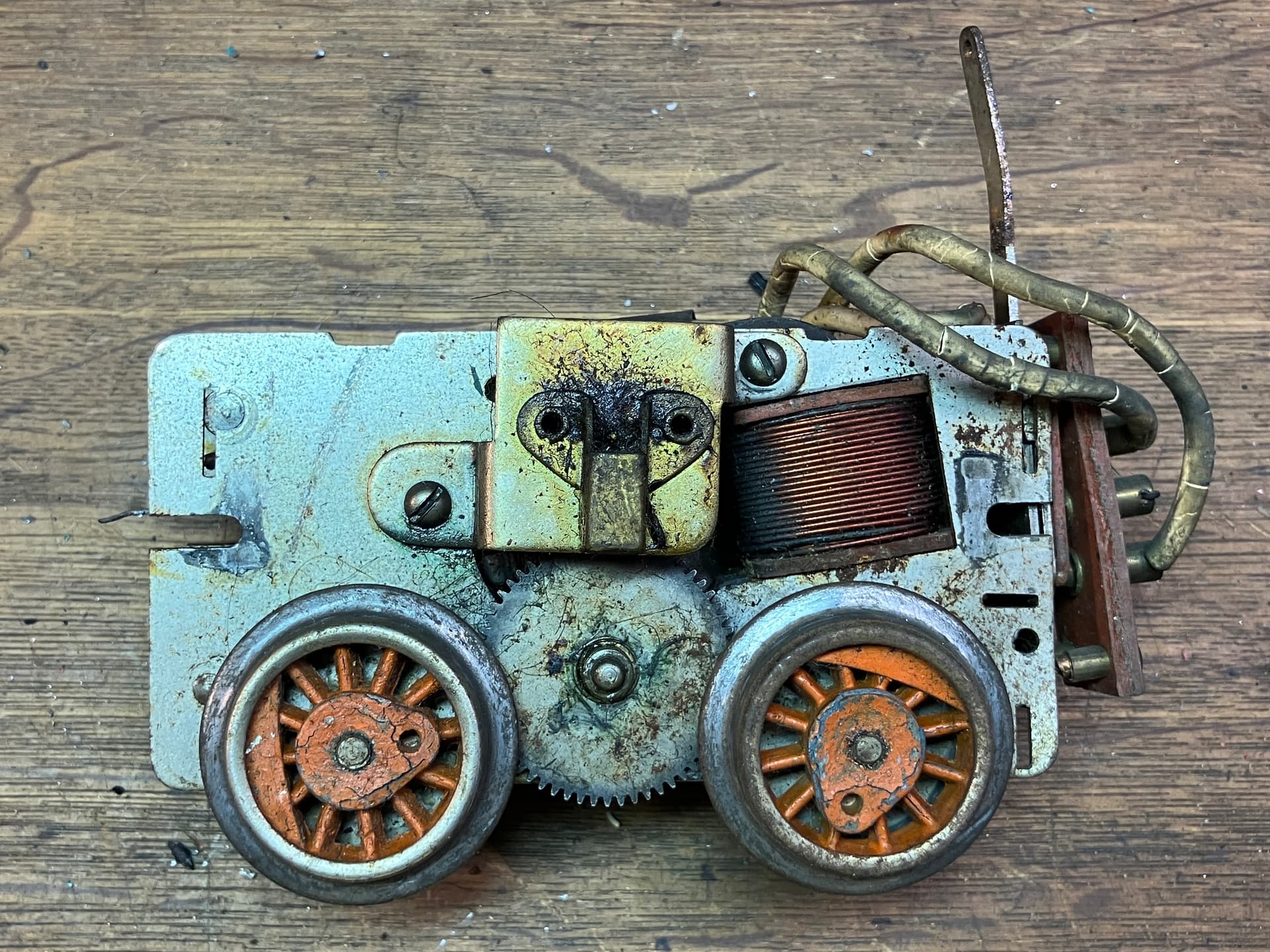
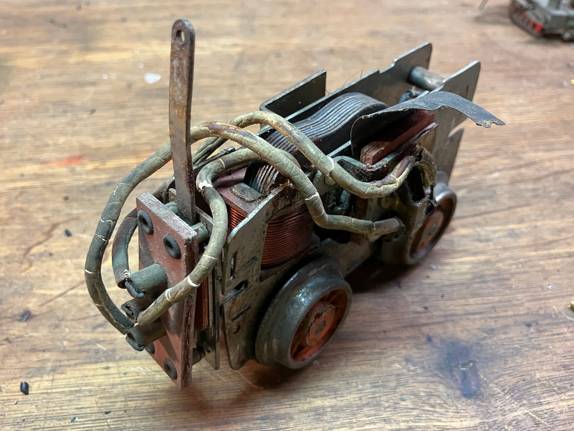
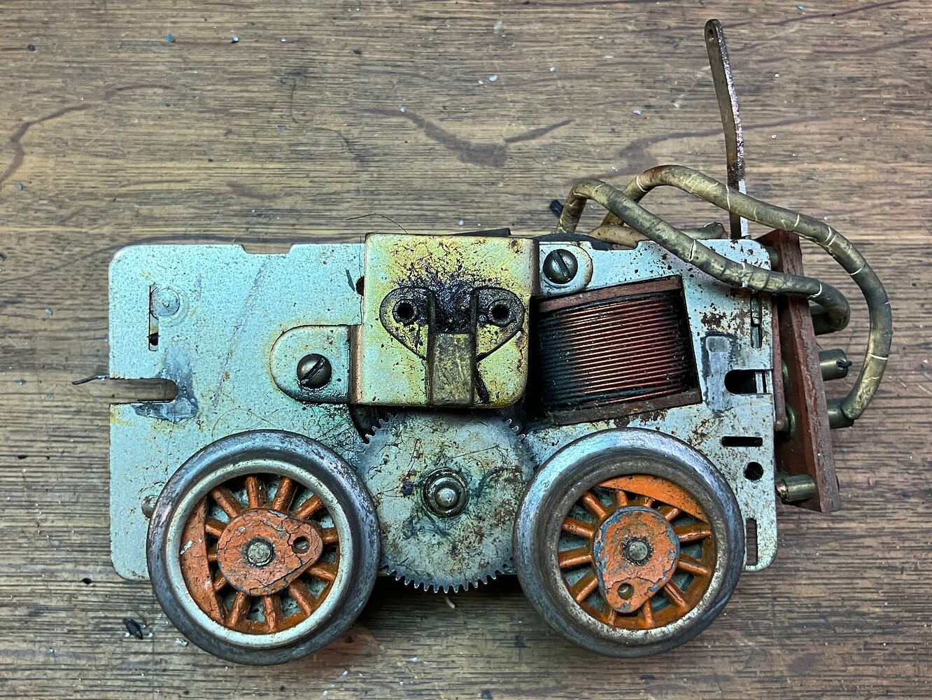
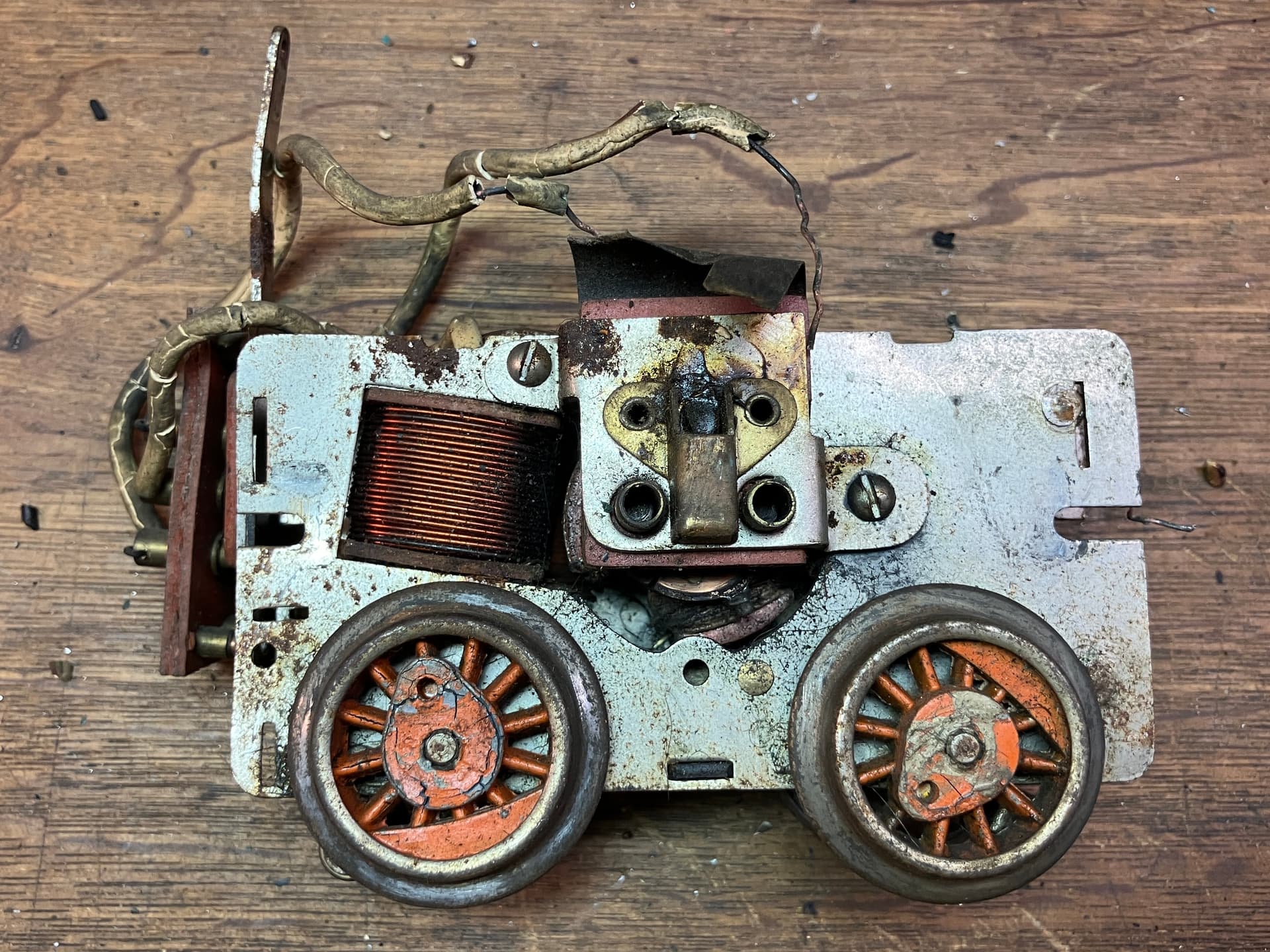
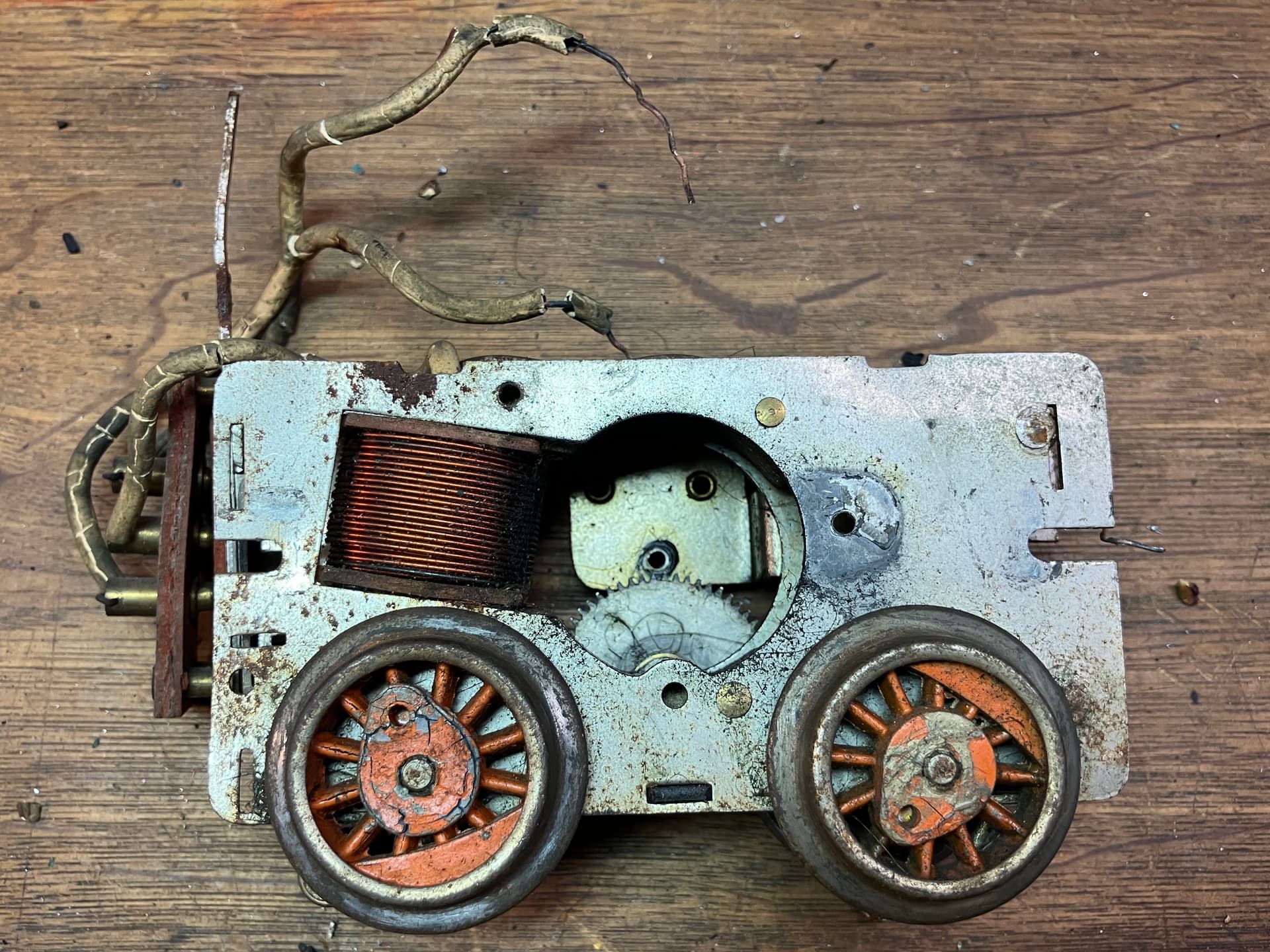
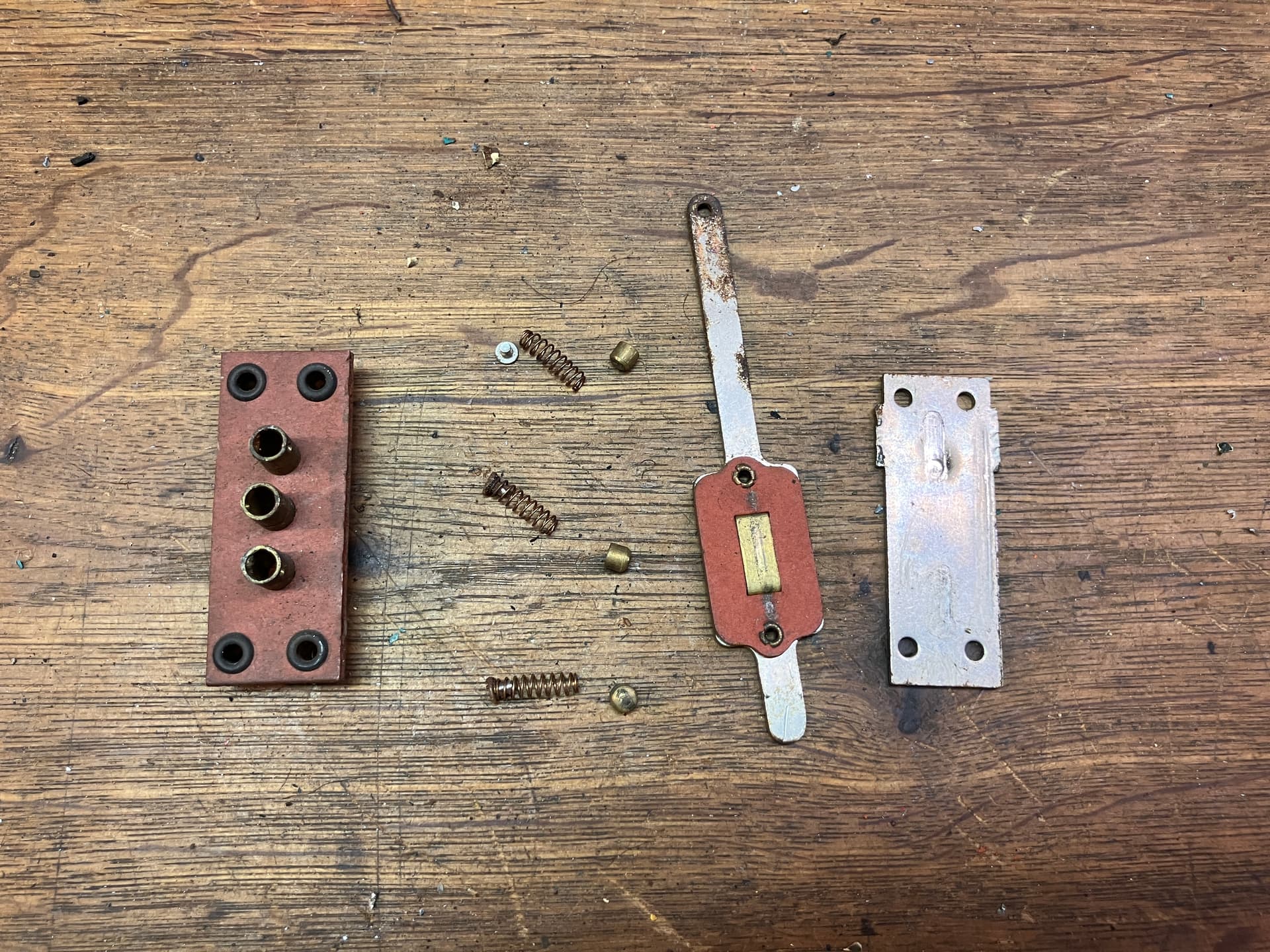
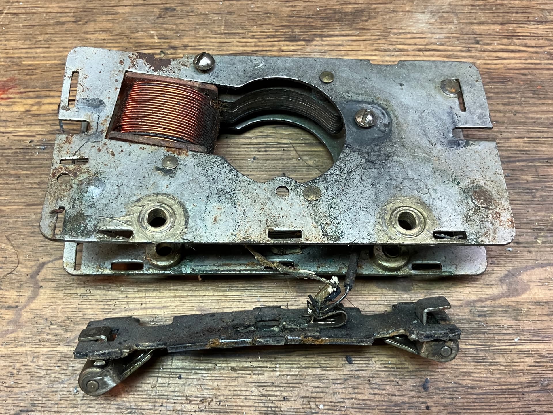
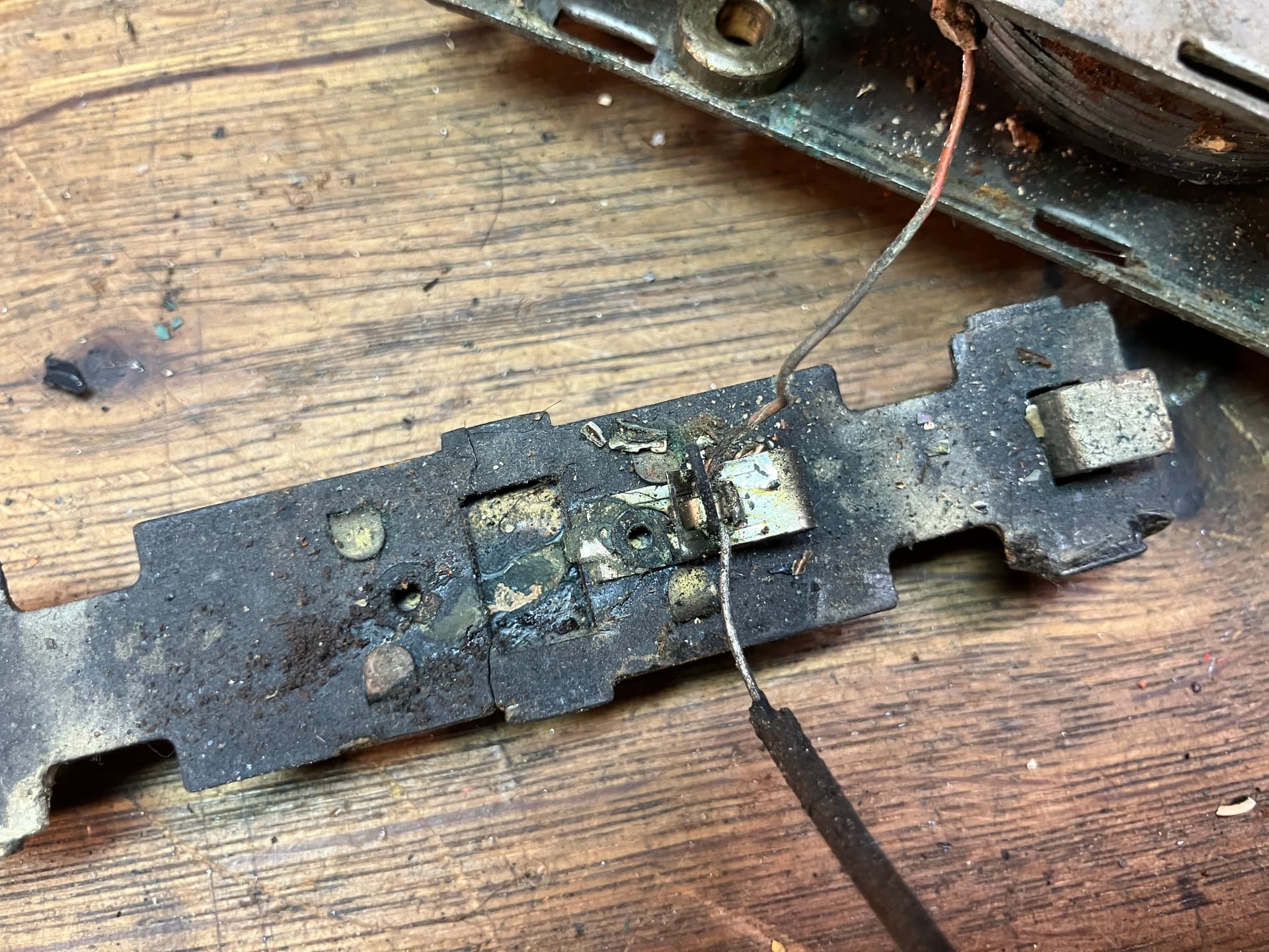
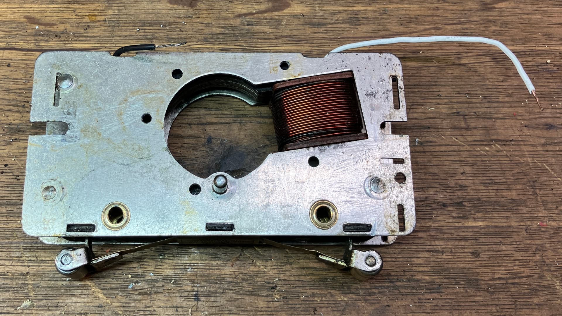
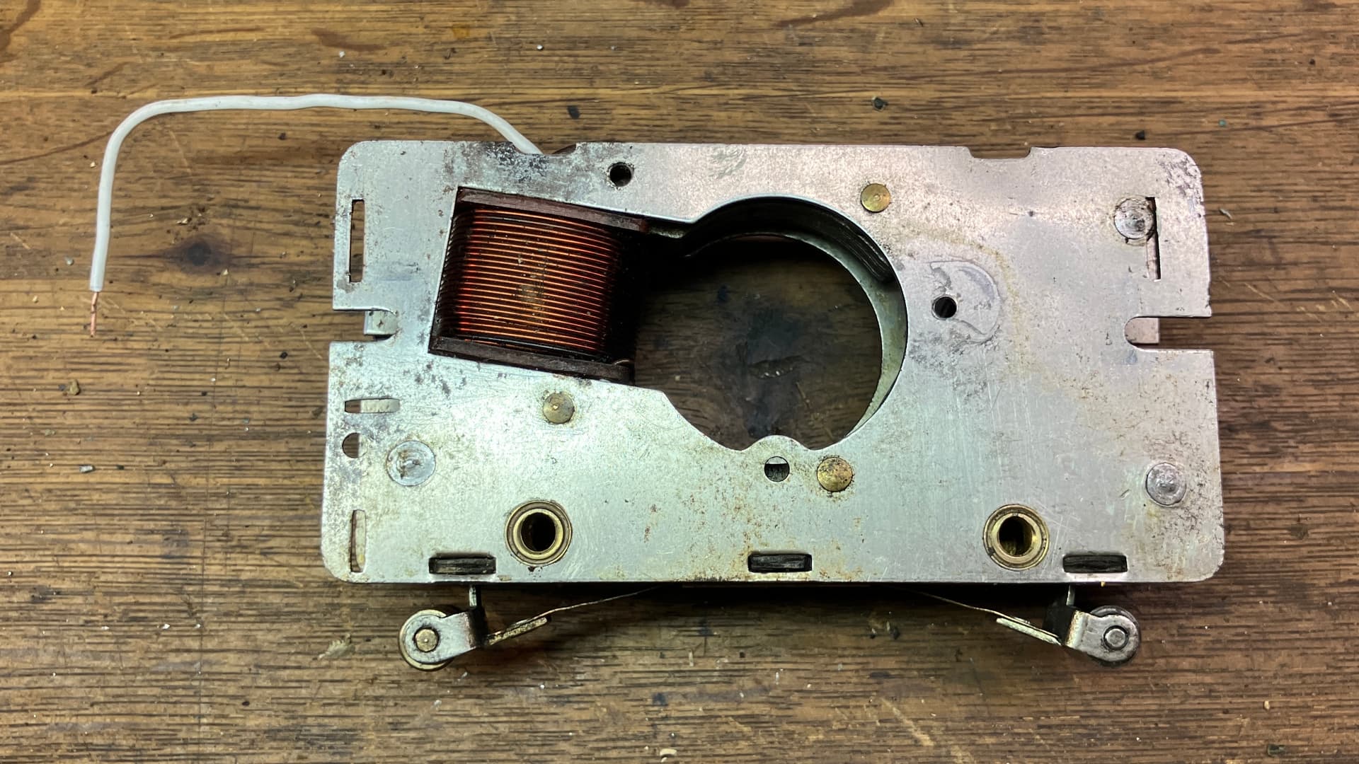
I went ahead and did the other wheel, then put everything back together for a test (the wheels needed to come off again later). By this point, I had cleaned the armature, brush plate, and reverse switch for the motor, and re-insulated the wires. As you can see… the test run was a big success!

If you look close, you can maybe spot that one of the gears was loose on its axle. Fear not! As we speak, the wheels are currently off the motor, and when they go back on, the gears will be properly secured.

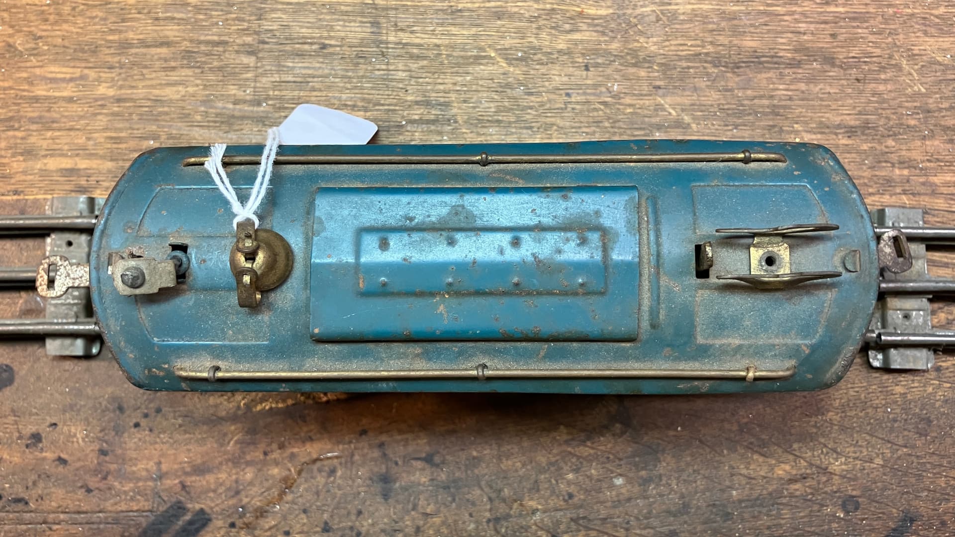
That’s all for now, stay tuned for more! The next update will cover the body and frame.

-El

4 Likes

And I’ll be waiting with baited breath for the saga to continue!
LOVE that deep AC motor growl, don’t you? :star_struck:

1 Like

What an incredible thread.

You say the way to begin is to begin but I don’t know how to begin. :rofl:

You are a true model railroader.

Rich

I realize that the above version of the research paper is missing all the figures! Here is a link where you can find the complete paper, with the figures referenced in the text: Corrosion-induced cracking of model train zinc-aluminium die castings
It is very interesting to look at the metallographic images of damaged parts, and visually see some of what is referred to in the paper.

-El

Parylene is interesting stuff.

Here is a basic introduction to its application, which is particularly useful because it shows the basic structure of paraxylene and the activated form of the monomer. Note the two stages of heating.

There are a number of variants of paraxylene that can be used, denoted by capital-letter combinations.

As noted, any residual moisture in a Zamak part, even deep in the nooks and crannies, can be removed during the vacuum pump down prior to CVD. Even if there is subsequent change in the structure due to low-temperature phase change (e.g. in tin) the conformal coating should prevent subsequent wicking-in of moisture.

1 Like

1 Like

Bravo Zulu, Ellie!