I just got a new set of fingers for the e-unit and installed them on the e-unit in the tender of my American Flyer #312 steam engine.
At first, everything seemed to work fine, but I noticed that the engine would abruptly stop and then go into reverse. Initially, I thought the track was at fault because it seemed to stall at the same spot. Each time that I would reset the transformer, it would cycle back to forward and run a litte before stopping and going into reverse again.
So, I took the engine and tender off the track, played witht the e-unit a little, making sure that everything was tight, and then put it back on the track. Ever since, I can get the engine to run in reverse, but not forward. All of the connections appear to be tight and the fingers seem to be sitting firmly on the drum. When the engine runs in reverse, it is flawless, never stops. When I cycle the e-unit to forward, it clicks but the engine does not move and the headlight does not come on. So, the 4 cycles are neutral, nothing, neutral, forward.
Is it one of the fingers, the drum, the wiring? Any help or suggestions would be appreciated.
Ok. First, I’m going to nit-pick because it’s a pet grudge of mine. Although lots of people refer to the American Flyer mechanical reverse unit as an eunit - that is a misnomer and a Lionel term. American Flyer trains use a mechanical reverse unit. Stepping down off soapbox now to give you some things to check. Apparently, track voltage is not reaching the loco when the reverse unit is in a certain position. Several things to check. First; make sure it actually IS the reverse unit at fault. Do that by disconnecting the tender and jumping the ports on the jack panel of the loco. Jump port #2 with port #3 (two inside ports). Feed your transformer leads to port #1 and port #4 (two outside ports). The loco should run in either forward or reverse. You can wire the male part of a jack panel as a tester for future use. If you do, use a red wire on port #1 and a black wire on port #4. That way, you can first check for forward by putting the red lead on the variable post and the black lead on the base post. Swap them to test for reverse. Let’s assume the loco works just fine. Second; make sure that the fingers are actually making solid contact with the drum. I know you said they were, but sometimes it looks like they are, but they actually are not or not enough to make good electrical contact. The trick is to have the fingers make solid contact, but not SO solid that they impede the drum from revolving. Third; make sure that the fingers are not slightly out of alignment so as to miss the metal parts of the drum. The second and third things are really two different issues. It is very unusual for a four-position reverse unit to slam directly into reverse from forward. I would expect that of a 2-position reverse unit as found in the Franklin. Fourthly; make sure the wires are soldered on their contact points securely. I don’t think
Didn’t you mean to ask for proof that it was ever called an e-unit? Every mention in my K-Line American-Flyer service manual calls it something else. Usually it is “Remote Control Unit”, but sometimes “Remote Control Assembly”, “R.C Unit”, or just “Remote Control”, and once “Remoct Control” (for the 21088 and 21089).
I have always tried to avoid using the term “e-unit” for Flyer; but I wouldn’t be surprised if I slipped once or twice. I have a few of them on hand, for fitting into tight spaces in O-gauge trains, like a certain very small ETS diesel. But I’ve never put one into a Lionel–the transplant would probably be rejected. I think the Flyer design is better than Lionel’s, using only 4 fingers instead of 6, to do the same job.
Ok. First, I’m going to nit-pick because it’s a pet grudge of mine. Although lots of people refer to the American Flyer mechanical reverse unit as an eunit - that is a misnomer and a Lionel term. American Flyer trains use a mechanical reverse unit. Stepping down off soapbox now to give you some things to check. Apparently, track voltage is not reaching the loco when the reverse unit is in a certain position. Several things to check. First; make sure it actually IS the reverse unit at fault. Do that by disconnecting the tender and jumping the ports on the jack panel of the loco. Jump port #2 with port #3 (two inside ports). Feed your transformer leads to port #1 and port #4 (two outside ports). The loco should run in either forward or reverse. You can wire the male part of a jack panel as a tester for future use. If you do, use a red wire on port #1 and a black wire on port #4. That way, you can first check for forward by putting the red lead on the variable post and the black lead on the base post. Swap them to test for reverse. Let’s assume the loco works just fine. Second; make sure that the fingers are actually making solid contact with the drum. I know you said they were, but sometimes it looks like they are, but they actually are not or not enough to make good electrical contact. The trick is to have the fingers make solid contact, but not SO solid that they impede the drum from revolving. Third; make sure that the fingers are not slightly out of alignment so as to miss the metal parts of the drum. The second and third things are really two different issues. It is very unusual for a four-position reverse unit to slam directly into reverse from forward. I would expect that of a 2-position reverse unit as found in the Franklin. Fourthly; make sure the wires are soldered on their contact points securely. I don’t think
Rich, Check the tension on the fingers on the drum. It is not uncommon to have a newly installed set to be out a bit. If you have a finger that looks a little different pull off that board and look at the board from the side. The fingers should have about a 10 degree angle from the neutral plane of the board toward the drum. Did you clean the drum? There may be some dirt on part of the drum. Let me know how this works out.
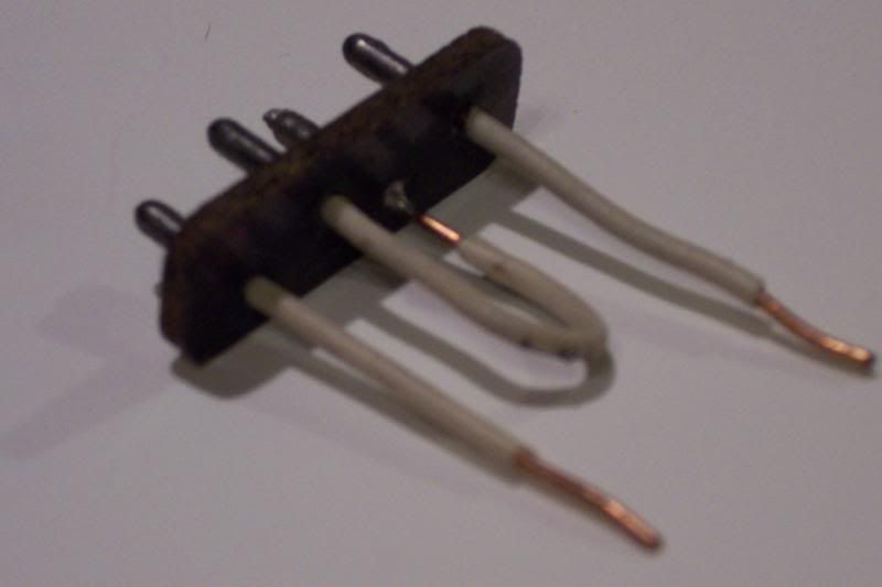
Here is a picture of the jumper that is talked about above
In reading timboy’s comments I’ve found it very true…I’m new to fixing vintage Flyer S gauge but have worked on tons of postwar Lionel. The Flyer stuff is quite finicky by comparison my short experience, but I do love that Flyer “look.”
That being said, am I correct in understanding the picture of the jumper provided above can be used to bypass a Flyer reversing unit and test the motor directly? Like I said just getting used to these engines and the signal flow is not as straightforward to me.
I am the last guy who should be responding to your question since I am still in the learning process and, as a result, far from being even remotely considered an expert. However, from my personal experience, thanks to the fellas on this forum, I can assure you that the jumper can be used to bypass the reversing unit and test the motor directly. I have done it myself. In fact, as it was first explained to me, there are four ways to wire the jumper.
The method shown in the photo will make the motor go forward. So will placing a jumper to connect the outer two positions while wiring the inner two positions to the positive and negative sides of the power source. To reverse the motor, you can place a jumper between the two positions on the left side while wiring the two positions on the right side to the positive and negative sides of the power source. You can also reverse the motor by placing a jumper between the two positions on the right side while wiring the two positions on the left side to the positive and negative sides of the power source.
What I love about Jim’s photo is the fact that a few scraps of heavier gauge copper wire can be used as the jumpers. When I first tested my American Flyer motor on my steam engine, I was using alligator clips which were tough to work with since they kept falling off the jac
Tim, the DPDT wiring you described puts the field in parallel with the armature, which is not the way the motor is meant to be wired. It is a universal motor, which should have the field and armature in series not parallel. If you use the DPDT to wire it in series, then there is no danger in the center-off position, because the entire motor circuit is open, just as it is when the reversing unit, acting as a DPDT switch, is in the neutral position.
There are various ways to wire the switch. Here is one: Wire the switch’s corner terminals diagonally to each other. Connect the armature (brushes) to the two diagonal wires. Connect one transformer terminal to one of the switch’s center terminals. Connect the other center terminal to one of the field pins. Connect the other field pin to the other transformer terminal.
If I’m not mistaken, the field pins are at the bottom of the plug, and the armature pins are at the top.