I have several lift outs along the backside of my layout. They measure 16" X 32", which is no problem for my body to fit through ( I am not a haystack Calhoun). What I am looking for, is any helpful hints for those of you modelers who “have” used lift-outs, in particular, the track wiring. What I am considering using at this point in construction are, push button contacts to cut power when the lift-outs are removed.
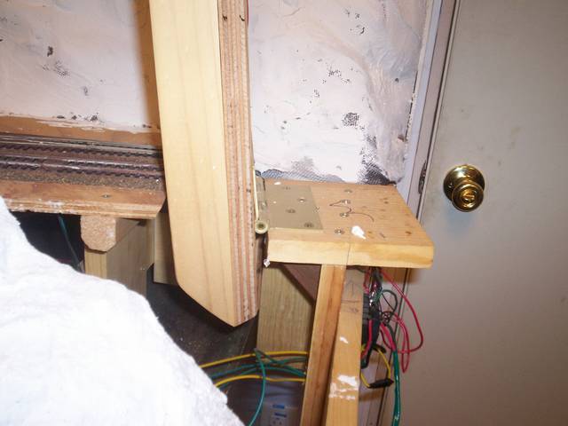
All of my lift-outs have been on wood bases, so this may or may not work for you. I have one lift-out and a drop-out. The liftout has tabs that it rests on when it’s in place. In the left and right front corners are 2 metal tubes secured to the benchwork, 1 in each corner. The left one has the ‘HOT’ wire connected to it and the right one has the ‘GROUND’ wire connected to it. On the piece that lifts out are two 2 1/2" long nails, one on each front corner. These fit into the metal tubes and convey power to the structures on the lift-out. The drop-out is wired in a similar fashion. It’s held in place by three barrel locks on the underside of the layout. One at the rear, one at the left front and one at the right front. The left barrel lock has a ‘HOT’ wire connected to it while the right barrel lock has a ‘GROUND’ wire attached to it. When the drop-out is in place, the barrel locks are inserted in their clasps which are connected to the structures up top by wires. Simplicity is the best way.
I don’t have any “lift-outs,” but I do have a bunch of “lift-offs.” These have no track, and they only provide access to subterranean rails below them. Most are made entirely of foam. The whole trick is to hide the seams where they join the rest of the layout.
I have developed a technique that’s worked for me. First, I cover both sides of the seam with a skim-coat of Gypsolite, which gives a gritty, uneven “ground” texture. Next, I put a piece of plastic wrap (Glad wrap, Saran wrap, etc.) over the gap on the non-moving side, and then I apply a layer of plaster cloth over the entire gap. Once the plaster cloth hardens, I’ve got a thin shell which bridges the gap. I hide it further with a lot of “shrubbery,” to quote the famed Knights Who Say “Nee.”
I have a lift-out section in the entrance to my train room. It has been in place now for about 3 years. One thing I have noticed is that there are changes over time that can cause the tracks to not stay perfectly aligned. I assume it is due to natural changes in the wood. My lift-out sits on a pair of tapered wood wedges. This way it just drops into place. To account for the seasonal changes I just glue on thin strips of bluefoam to get things in the right place.
Taking a hint from a MRR article, I have used Atlas re-railers cut down accross the joints to help with the transition.
I also have a pair of switches that kill power to the 2’ of track either side of the lift-out if it is not in place. I don’t want the kids running trains into oblivion!
I have a lift out in a corner of my layout with some industrial sidings on them.The track slightly overlaps on to the fixed portion of the benchwork and the ties are undercut so the rail joiners can be slid under them to disconnect the liftout track. Styrene pavement on the liftout also overlaps onto the fixed benchwork to hide the seam. The liftout itself is two inch foam glued to wooden rails that are screwed to the benchwork so that when the liftout is put back into place, the track will be in the same allignment.
I would not elect to use the rerailers for a number of reasons. First, they look out of place on a layout, unless you can convincingly make them look like a level crossing. Secondly, cut down the way shown above, it would look even more contrived. Thirdly, they do not aid in keeping the train on the rails as well as I would like…but that is quibbling. Finally, if you have ever had occasion to look closely at the bridge rails on a Walthers built-up turntable, they are heavily beveled on their inner flange faces at their ends. This, to me, would be the best solution to ensuring successful transition to and off of the bridge. If one uses hardwood blocking on which the bridge is to rest, it should fit essentially the same way time and time again. With extreme shifts in either temps or humidity, the latter by far the more serious factor in wood, there may be slight increases in slop such that the rails might misalign by 1/32", give or take. This is exactly the purpose of the inside bevel that works so well on the turntable.
On the basis that a lift-out section across a door is not exactly a prototypical look I’m not all that bothered by the track-work not looking prototypical in this particular location. In the MRR article one of the benefits they stressed was that the rerailers could help avert a disaster by getting a derailed car back on the track prior to crossing the lift-out. This has certainly been the case in my experience. They have worked very well as advertised. We all make compromises all over our layouts, this one was not a real issue for me.
That’s cool. I know that we all glom onto ideas and methods that seem reliable to us when things really count, and this is no different. I hope, too, that you weren’t miffed at my “dissertation”…[:D] Boy, this hobby is such a personal thing, isn’t it? Touches the very core of us.
The rerailers are apparently the thing to have in a tunnel, so this seems to fit.
Not miffed at all my friend! Actually thought it was rather amusing, nothing wrong with expressing an opinion and you left little doubt what yours was!
We seem to have two answers going at the same time…my initial question dealt with lift out sections at the rear of my 4x8 tables in case of repairs etc. Selector and Jeff addressed that issue as well as Mr B, however others may have more ideas, and certainly the more the better.
The second set of replies seems to be dealing with a lift out, lift up, or swing down section, to allow entrance to the walkway in the middle of the surrounding layout. Although I did not ask about that problem in particular…I do have that problem facing me also. My wife said," why don’t you just duck under it"…well, yes, I can sit on a stool with rollers and spin myself under, or I could get on my hands and knees each time and crawl under ( nice on cement floor with very thin carpeting and no padding ), or just take my chances and duck under and hope I don’t arch my back too soon…“ouch” !!! Can a 5’-9" 185 lb guy do this every time??? Probably…is it smart? NOOOOOO!!
Here is the issue. My table top is 3/4 plywood, with 2" of foam glued to that. If I swing up, I will have to remove about 6" of foam on the bridge or the table top at the HINGE end for obvious reasons…it will bind if not cut back to allow for the 2" thick foam.
A swing down would eliminate that problem, but, allows for people to damage the swing down if not careful walking through the open space.
If I go to a LIFT OUT bridge, then I don’t have to cut foam, I just have the inconvenience of trying to find a safe place to lay the bridge unless of course I am just replacing it right away. However, this repeated motion will, over time, allow for excessive wear and easier damage if not placed in proper position carefully each time.
Trust me, I ding my back at least once a week, and I am a shrinking 5’ 7.5" who has to duck under 43". It is no longer a probability when you are turning the air blue and rubbing your back. But, I wouldn’t have it any other way unless I were content with 16’ of L-shaped shelving and a point-to-point.
Anyway, if you were inclined, you could wax the areas of friction as you find in better quality bedroom furniture drawers. Or, perfectly fine too would be using thin nylon flat bearings glued in the corners of your support structure. These would reduce your wear immensely.
That is very good advice young man, I have taken note and will place that in my folder of "what to do " when I approach that part of the construction. What was funny at Christmas time when my #3 son came downstairs to see the room, is that he asked “why the ceiling was so low”. I explained that:
When the addition was added, I made sure that the cement floor was 1" above the Utility room floor adjacent to the train room in case of water leaks from boiler, well storage tank, water line breaks, or DHW tank leaks, as well as washing machine potential floods.
That left a working height of 6’-11" to the bottom of the 1st floor joists.
You need 4" minimum to hang a suspended ceiling, leaving 6’-7".
Son, you are 6’-2", and being the tallest of the family by over
On the issue of the lift up - install some 2" or higher blocks on which to mount your hinges. If the hinge axis is above any scenery, track or support at the joint then you will not have to cut anything back. The drawback is that the hinges now become fairly prominent visu
FWRIGHT: I have come to the conclusion, after reading all the horror stories of many modelers ( all over 40 ), that duck unders are to be avoided at all cost. So, I have removed that as an option.
Now, I need to see if a lift out has merits. The opening is 30" wide, and the width of the bridge would probably be triple track. The material that I am using for table top is 3/4" plywood with 2" of foam on top, so this should not be very heavy to lift out. Considering that I routinely lift 16" logs of oak onto a log splitter, a little 30" by say 24" bridge should not pose any strain on me.
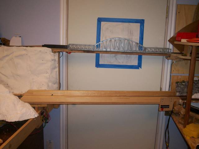
Here are two of my straight track lift ups (swing ups) and also have two that have a 90 degree double track turn on them. What I really enjoy about mine is that that they stay upright (open position) accout of going over center in up position. Work well, very quick, and bullet proof.
Grayfox1119, many excellent suggestions posted here and I will add another. Many years ago Stanley made a side mount hinge sort of/ kinda like the one on a refrigerator door. Very stiff with no slop in it, and very little of it can be seen and then only from the side if you don’t senic it. It has provided many years of reliable service for me. I don’t know the Stanley part number, but I am sure a dealer could look it up and order it for you. Worth a look see. Second, (and this is not my idea, but one from a magazine) place brass screws into the wood under the each end of each rail and adjust the height of the screw until it just touches the bottom of the rail. Now solder and this will result in perfect alignment with no movement of track. Now expansion and contraction of the wood, ah well that’s always an ongoing situation, isn’t it.