Hi again everyone, I recently purchased 3 aspect block signals. I programmed my arduino to work them with ir sensors. They worked fine until I installed them on my layout and hooked them up to my dedicated buss wire for my signals. The buss wire gets its power from a computer atx power supply and is DC current. I have not installed my arduino yet on my layout. I found out that these block signals work on ac current not dc current. I emailed the manufacturer of these block signals and inquired about converting them over to dc current. He told me that I could remove the resistor on the black negative ground wire and install the resistor on to the bulb side to get them to work off dc current. I have a number of questions about this. First, does a resistor has to be on every aspect (green, yellow, red) ? Second, can I power my arduino with the computer atx power supply? Third, will the block signals work as they should if the arduino can be supplied with power from the computer atx power supply? Or do I have to scrap this and start all over and do these block signals a different way all together?
I’m in the process of installing my Arduino powered block signal system. I’m using an Arduino MEGA for my signals.
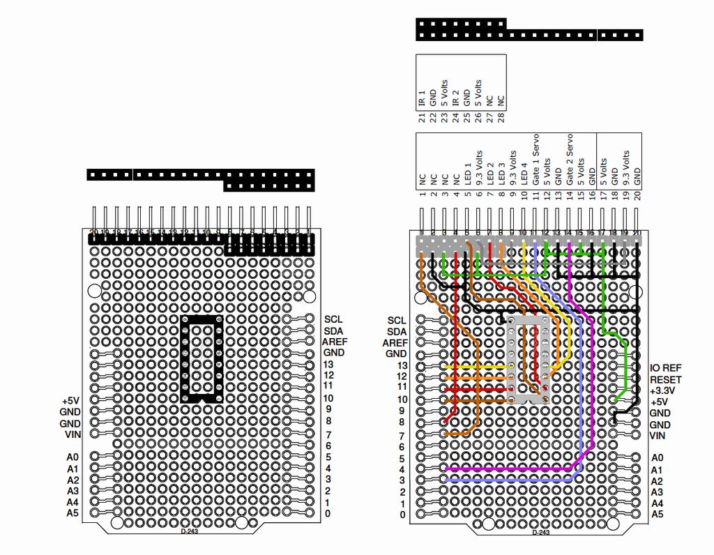
The Arduino will work from 6 to 12 volts DC using the round power connector. If you power it from a side connector pin it must be +5 volts. If you are using the Arduino to power your signals make sure you don’t exceed the maximum Arduino output current, the max current per port is 40ma. I wouldn’t go with more than 25ma per port to be on the safe side.
EDIT:
The picture above is my UNO Gate Controller shown to show the +5 volt & Ground side pin connections. Double click to enlarge.
The computer power supply should have a regulated +5 volts output. If you power the Arduino from 6 to 12 volts make sure your +5 volt total current doesn’t exceed 450ma. The internal 5 volt regulator is rated at 500ma including the Arduino Processor (45ma).
<
I didn’t address your AC signal problem. I don’t understand why it won’t work on DC and changing the resistors shouldn’t have any effect on the lights. Make and model of the signal might help.
Mel

My Model Railroad
http://melvineperry.blogspot.com/
Bakersfield, California
I’m beginning to realize that aging is not for wimps.
can you post a link to the type you have
each LED should have a resistor (if in doubt, start w/ 1k) should only draw ~10ma. bulbs? how much current do they draw?
instead of an ATX, you might consider using a typical USB AC adapter (this one provide 2A)
i would connect the ground side of the LEDs to the Arduino output (active low) and provide power (Vcc) to the LEDs from the 5V of the Arduino.
Somethign else to remember is there are two ratings for the power available to the outputs - there is the max per an individual I/O line and there is a maximum for the entire microcontroller. While an individual line may be able to handle 40ma, you can’t load EVERY line to 40ma, or the chip itself will still fry. It shouldnt be a problem with LEDs, 40ma would fry the LED< so the current needs to be limited to something less. Plus with 3 LEDs per signal head, it’s not likely that all 3 would ever be on (unless you program in a lamp test button), so only 1 in 3 I/O lines will generally be active. Plus if some of the lines are used for inputs from detectors, that further reduces the total output power needed.
It is something to consider if most or all of the lines on a given Arduino are going to be used as outputs to turn something on.
–Randy
Randy
I’m using a MEGA for my controller and driving the LEDs direct from the Arduino outputs, switching ground. It is configured to drive 16 searchlight signals using SMTL4 RGY LEDs. Green draws 2ma, red draws 4ma and yellow draws 13ma. Those currents are for equal brightness to my eyes.
I have never seen a published total current of the Arduinos only the max 40ma per port. I rarely run more than one train at a time so with a long train the max yellows on simultaneous would be one with two red and 13 greens for about a total of about 35 ma. Two trains would double that to about 70ma.
I have seen the max total current of the internal 5 volt regulator at 500ma with a warning of board heat dissipation but nothing on the max CPU source switching current.
I’m powering the 5 volt LED supply voltage direct from my 5 volt high current source and switching ground to the LEDs with the Arduino. I’m not using the internal 5 volt regulator for any external power.
I’m also using the high current power supply to power the FC-5
sect 28.1, pg 258 of the ATmega328p datasheet has a table indicating max current per I/O pin of 40 ma and (max) “DC current Vcc and GND pins” of 200 ma. same limits for ATmega1284p used in Arduino Mega.
drawing 10 ma from 16 I/O should be < this limit. (not true for mega)
Here is a link to the block signals I purchased they are Evemodel block signals.
JTD873GYR. description mentions common anode and cathodes for each “light”. Of course, LEDs can be driven with AC. Different size resistors may balance intensity as Mel said.
The signals you purchased have LEDs so they are usable with an Arduino from the 5 volt source with the proper resistors. The listing says they are AC or DC so something must have been twisted in translation.
LEDs are polarity sensitive on DC. According to their listing the black wire is positive and the colored wires are negative. Assuming that your Arduino is switching ground the black wire would go to the +5 volt on the Arduino and the colored wires to the output pins (with a resistor in series). As only one color is activated at a time you could put a single resistor in series with the black wire.
The LEDs that I’m using require separate resistors to get equal brightness from the three different LEDs. The current needed for equal brightness is different for each color LED. The red and green will be close but the yellow will be much dimmer using the same resistor value.
Mel
&
I use an Arduino prototype PCB for all of my Arduino projects, much easier than just wiring goodies to the Arduino pins.
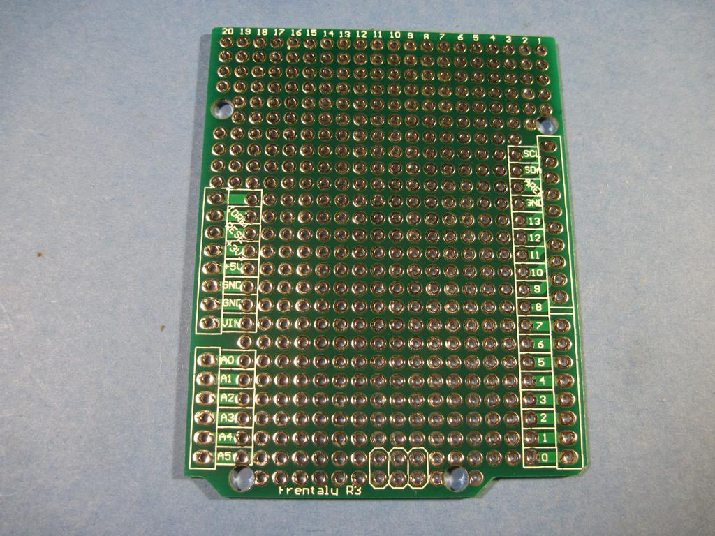
They do not come with connectors. I buy the 40 pin strip connectors and cut them to the length or pins nee
Yeah that seems to be one of those technical bits they hide in the interests of keeping the Arduino “simple”, but the datasheet of the actual microcontroller has the info.
–Randy
Thanks for all the help!! What I am planning on doing is supply the arduino with a arduino power supply instead of the computer atx power supply. I have a 4 x 8 layout HO scale with 3 block signals for the main line. I am planning on hooking up the arduino to terminal strips that I have placed at the block signals under the layout, then running the block signal wires to those terminal strips. I will then place terminal strips for the ir sensors and do them the same. Will this work? or would I have to do it another way? It sounds like the computer atx power supply will be too much for the arduino and the block signals together.
Sounds like you know what you are doing. A simple USB charger would work to power a single Arduino. I would suggest you size the resistors for the same brightness before you install the signals, it will be a lot easier to make all three colors equal. Green is the most efficient then red. Green at 2ma then red at about double at 4ma, the yellow LEDs take from 9 to 12ma to equal the green and red.
Mel
My Model Railroad
http://melvineperry.blogspot.com/
Bakersfield, California
I’m beginning to realize that aging is not for wimps.
I would definitely use a proper rated 5V power supply for this sort of thing. The on-board regulator ont he Arduino has no heat sink and is a low power device, so feedign 12V and relying on that regulator to power the external devices attached to the Arduino is generally a bad idea. It’s fine in the “experimenter” stage doing the sample projects with one or two LEDs, but higher current devices, even a 9G servo, can have problems workign reliably powered through the Arduino.
The best way to power things is use a 5V power supply, and connect it to the 5V and GND pins on the Arduino (don’t get it backwards). Forget powering through USB, or through the other input that can take up to 12V DC. Then the only thing you need to consider is the load per pin and the total load of all pins.
–Randy
while the Atmel processor is designed to operate over a specific range of voltages (max 6V), the Arduino is designed to operate from USB or 12V using the on board regulator.
why ignore the capabilities an electronic device is designed for unless you’re not confident what they are? (see Feeding power to the Arduino)
in many cases it makes sense to use a supply higher than needed for the processor. A DCC decoder relies on the ~14V available from the track to power the ~12V motor. The decoder has a regulator for the processor which doesn’t require much current so there shouldn’t be that much wasted power using a linear regulator.
if 12V is available on a bus going around the layout, why not use it. Power thru the regulator can be minimized by powering external devices (e.g. signals) from 12V and controled using a grounded output so that the I/O current is not drawn thru the regulator.
I agree to some extent. I started out using 12 volt Grain of Wheat bulbs on all of my layouts since I went with HO scale back in 1951. I still prefer incandescent bulbs for my structures and street lighting over LEDs.
It’s all fine for the experimental stage, but that little SOT-23 regulator on the Arduino (well, on the Nano anyway) doesn’t have much current capacity. The Uno has a bigger +5 regulator and so should be fine up to the limit of the ttoal load on the 328. They don’t explicitly tell you the limit of this regulator, but they do say that the 3.3V regulator is good for no more than 50ma - and it’s the same package as the 5V regulator on the Nano boards, so I’m assuming a similar rating. And the closer to the input limit, the lower the current limit, since
external devices (e.g. servo motor) should not be supplied power thru the arduino regulator, they should be supplied thru an external source. This includes LEDs.
contrary to what is said above, a 12V supply for a motor can be connected to the Arduino which uses it’s internal regulator for processor power. The arduino controls an H-bridge which has separate power for the h-bridge and for the motor which it controls. I doubt the h-bridge logic requires much power which could be drawn thru the arduino, but the motor is not supplied thru the arduino.
external devices can be controlled thru the arduino using active low (i.e. open-collector logic) so that current flows into the input, not out thru the regulator.
maybe servos should be power thru a lower (3.6V) external regulator to minimize current.
I’m just wrapping up my MEGA with 12 signal heads connected direct to the Arduino outputs and the total current (measures on the ground side of the LEDs) is 41ma @ 5 volts. I’m sinking the LEDs with the MEGA outputs. That’s 10 green 1 yellow and 1 red LED. The total Arduino current measures 93.8ma @ 5volts or 52.8ma for the MEGA board. Max current on one MEGA ports would be 13.5ma (Yellow), and two red at 4ma each the remaining 9 ports will be 2ma each.
A long train would have 2 red LEDs on increasing the current by 4ma, actually a green would be off with a second block red on so it would only be 2ma more.
My longest train will only occupy two blocks.
EDIT:
I forgot to include that the LEDs are not powered from the MEGA regulator, they are powered direct from the high current 5 volt power supply.