
I believe there are too many chef’s in the kitchen…
I also believe that the OP is calling an open, (no power) a short.
A track schematic is definitely needed, in this case.
Also if the turnouts are being used as a crossover and you want to power both frogs…two relays will be needed,(one can be used by using top and bottom of relay…just make sure you get the wiring correct) along with both rails insulated frog to frog, because the frogs will be a different polarity, DC or DCC when switched to use as a crossover. I have 8 crossovers made with #6 Atlas turnouts and they have performed flawlessly for over 25 yrs. wired as I described with Atlas under table switch machines and normally open push-buttons to control.
I hope You get it figured out…outta here!!!
Frank

Welcome aboard, Chef Frank! [C=:-)]
Rich
Crossover keeps coming up but I’m not see anything but a crossing on his diagram.
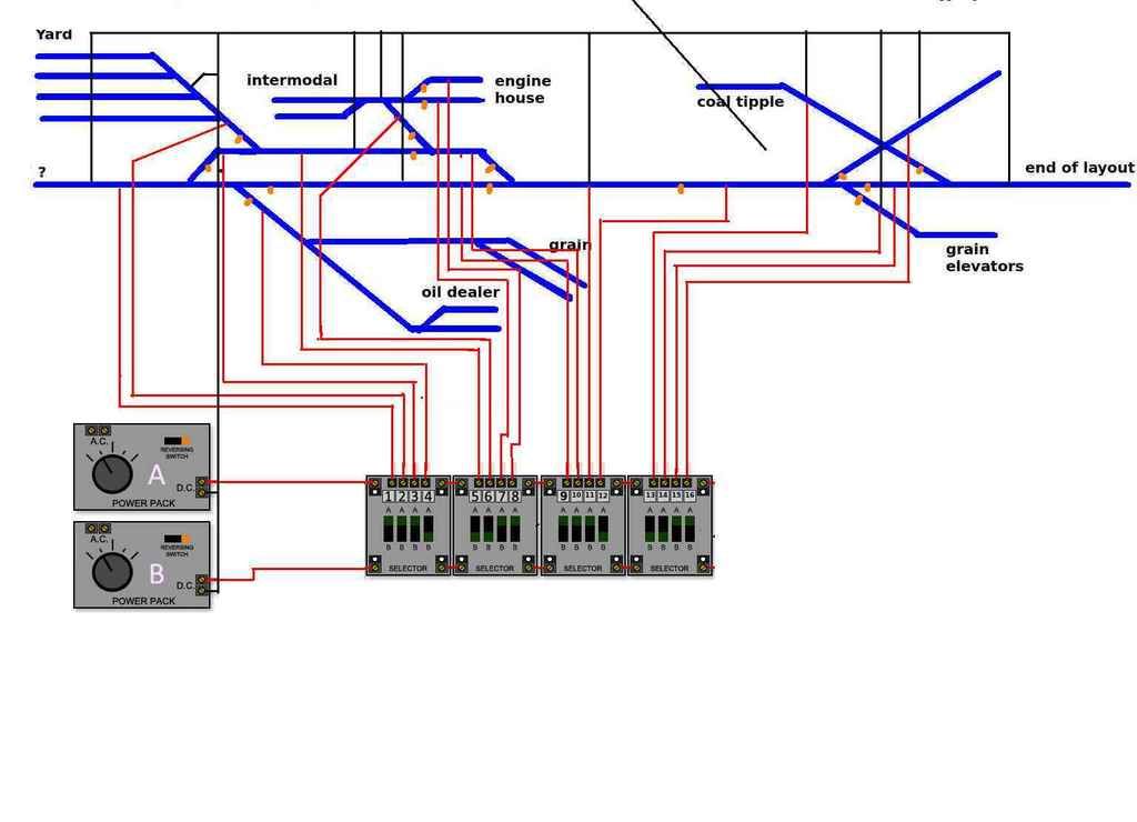
I think the Atlas component 2 cab thing is how his layout USED to be. Pretty sure he’s using DCC now.
If it IS still wired like that for DC, then if the connection between the two turnouts is the division between two blocks, then it would need insulated joiners. For DCC, unless there are multiple power districts, no insulated joiners are needed.
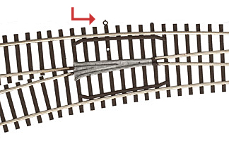
Now that it was brought up, I’m kind of surprised trains make it over where those feeders are soldered on the inside, it looks like there is practically no flangeway at all with the wire there. If there are stray strands fom one feeder sticking up, it could touch the wheels of a loco going down the opposite route and cause a short. Or if the solder joint obstructs the flangeway enough, the wheel could just climb up and lose contact.
–Randy
The photo with the two red pins (reinforced by the schematic) doesn’t show a crossover. Just two turnouts connected in a row. Since I don’t think that he has indicated where in the schematic this trouble spot is located, we’re all guessing.
Maybe he just needs power fed at the points end of the second turnout in line? The insulated joiners and Snap Relay are canards, perhaps.
The soldering skills, most definitely need a lot of improvement. I best be quiet…
#1 rule…(for Me).power from the point side of Atlas turnouts/all turnouts… especially power routing turnouts. I used to use a lot of original Shinohara turnouts, which were power routing with live frogs…
Good Luck! [:D]
Frank
What I noticed in the common rail diagram, was the fact that at the Intermodel section and Engine house section there are two turnouts point to point…they should be powered from the point side of the turnouts and if that turnout with the yellow & blue wires is where it is powered it will create a problem especially if the feeders are crossed.
Good Luck!
Frank
The reason I like these type of threads is I always learn something.
Aside from the fact that the departing frog rail is excedingly short on the #8 for feeder attachment, if Atlas turnouts are not power routing, why the point side?
If we don’t tell the OP his soldering is a potential problem, how’s he going to know?
Thanks to everyone for the sound advice. Atlas called me back and told me that I do need the Atlas switch (as was shown earlier). Sorry if the soldering has caused some laughter by those more versed. Soldering is far easier than it looks and having not done it, there is a level of finese and technique.
I’ll keep everyone informed. This is far easier to explain and resolve over the phone. Gotta love technology sometimes!
Much appreciate!
~Lee
Lee,
So what You are saying is what You are calling a short, is indeed the lack off power at the insulated dead frog and you need the relay to power it. Not hard to understand…#8 turnouts have a long frog.
Take Care! [:D]
Frank
Atlas even provides a soldering eye on their #8s and curved turnouts:
 Atl_curve by Edmund, on Flickr
Cheers, Ed
ED, Yes I saw that in one of His photos… I personally never had any need for #8’s. Number 6 has always worked well for Me.
Take Care! [:D]
Frank
That’s because for Atlas turnouts and other NON power routing turnout is this NOT true. You can (and I do) power Atlas turnouts with feeders on all 3 legs. The diverging frog rails of an Atlas turnout connect under the frog to the cloosure rail on the opposite side of the frog - liek the analogy I gave of the turnout being 2 pieces of straight track laid on top of one another. There is absolutely no reason not to power an Atlas turnout from anywhere.
You can NOT feed power from the frog side of a power routing turnout like a Peco Electrofrog. At a minimum, the two center diverging rails after the frog need gaps, and then any power for track past that point gets fed after the gaps. Never feed the frog side of such turnouts.
–Randy
Wow! What helpful information RRinker: Pls check your personal msgs.
Frank: Correct that what I’ve got is not a short, sorry for any confusion.
I think your problem is just the large, dead froog. The instructions for wiring the Atlas Snap-Relay were posted on the first page, I think if you do that, your problems will be solved.
Also, if you don;t want to solder to the rails, solder to the rail joiners - dooon;t buy the Atlas terminal joiners, they cost a small fortune and use really thin wire. Get a pack of regular joiners, cut and strip a whole bunch of lengths of your feeder wire, and sit at your workbench and solder away. Use a pair of these (one with each color wire - and make sure to keep the right color on the right side of the rails) for every, or at least most, rail joiners. I’ve used this method with great success on two different layouts now. No chance of melting ties, neatness only sort of counts. Those helping hands things with the alligator clips are handy for holding a joiner and a piece of wire, leaving both hands free to hold the soldering iron and solder. If you aseembly line it and make a bunch of stripper wires then solder for a while, you’ll have a stock of terminal joiners ready to go, all put together while comfortably seated, not leaning over the layout.
–Randy
Or, better yet, just solder the feeder directly to the rail. But, make sure you solder the feeder to the outside of the rail, not to the inside of the rail.
Rich
Kasskaboose,
Answered Your PM…CK msg’s for My reply…
Take Care![:D]
Frank