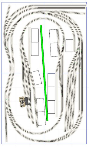
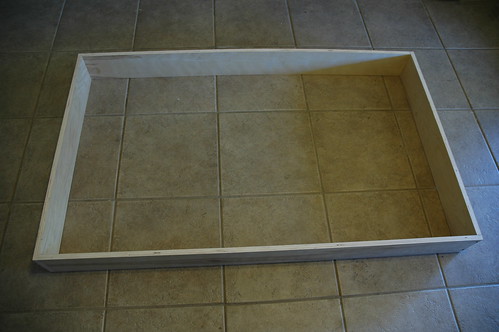
So lets start building a layout. The B&SW (above) has 4, 3’x5’ sections to make the overall 6’x10’ layout. Lumber is all 3/4 inch birch plywood ripped into 6"x8’ strips.
8’ strips were cut into 3’ and 5’ long pieces that were constructed into a box (pictured above)
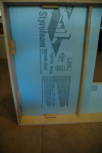
Since this layout is my first I wanted to try a few different construction techniques. The B&SW has two different tops, half the layout has a 2" foam top and the other half has 1/2" plywood with 1/2" foam top.
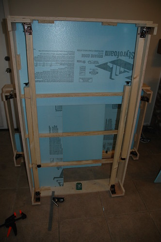
The picture above gives you an idea on how I braced the 2" foam top, the other half is braced similarly just feature the plywood and foam top.
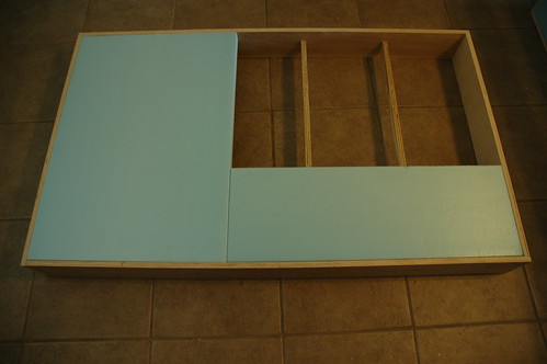
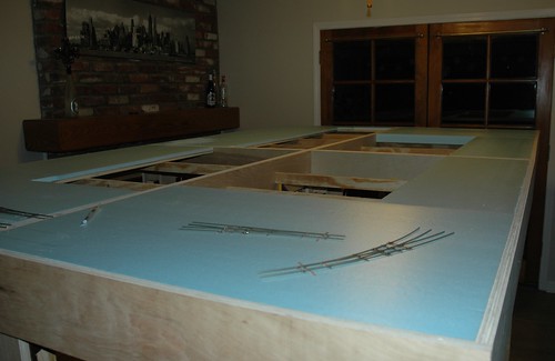
The top down view shows the other braces in the opening in upper right that will have the branch built at a 2" higher than the rest of the layout.
This picture shows the finish section with the hardware for the folding legs from Lee Valley Tools (PN 00T16.10). It also shows how close the legs are to touching to allow just enough clearance to allow them to close.
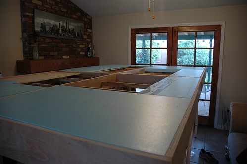
Final this gives you an idea of the simi-finish product, you can see the plywood top on the left and the foam only top on the right.
The final product is seen above with the foam top glued d
Looks nice so far, very clean looking job. I personally would add more cross bracing but thats just me I like to add the over kill factor into my engineering. If I may ask do you intend to have any scenery such as mountains, hills etc. if so what are you plans and what type of roadbed are you planning to use on the extruded foam?
The plan is to use the leftover foam to build the hills and other scenery elements. The roadbed is right out of the MR special issue of Realistic Reliable Track and will be campers foam tape with Homabed roadbed on top.
In regard to the campers tape the stuff usually found in the home centers isn’t wide enough, Cal Roadbed also overs a subroadbed that seems like a good product. I only use their roadbed on top of Homasote sub cut by yours truly
It’s a new year and time for an update on the B&SW!
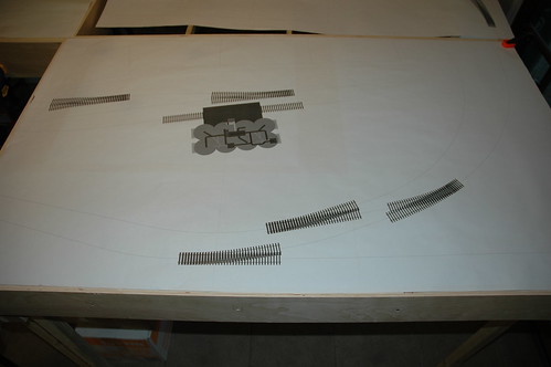
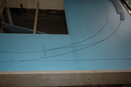
I spent a lot of time tweaking the track plan, about 25 different designs for the 5x9 and 16 with the 6x10 so I wanted to make sure that the plan transfered from screen to reality. The best idea I could come up with is to do a full size print of my track plan and use that to draw my track plan onto the bench work.
The image above shows the full size track plan laid over one of the sections of the layout.
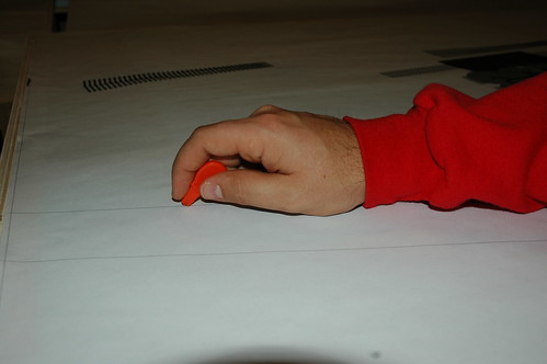
The next problem is how to get this plan on the foam. The solution I came up with was using a tool I got from a pumpkin carving kit. The kit came with a small tool that can be used to transfer the face templates onto the pumpkin. The tool has a small wheel with spikes on it. The idea is the spikes are large enough to puncture through the paper and into the pumpkin.
As you can see above I used it the same way to pucture through the paper onto the foam.
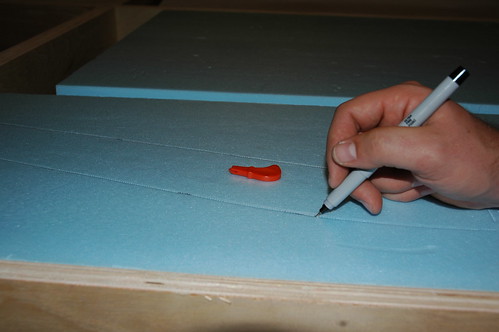
The image above shows the result of this process and traced with a marker
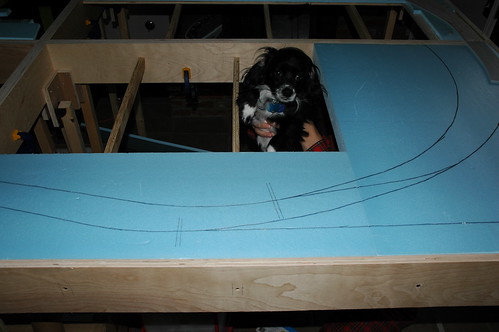
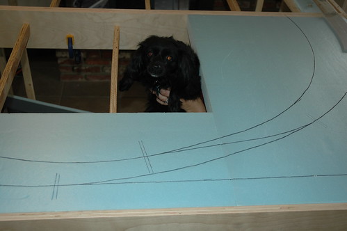
The three images above shows the results (and as you can see my puppies were helping)
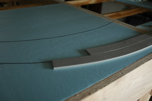
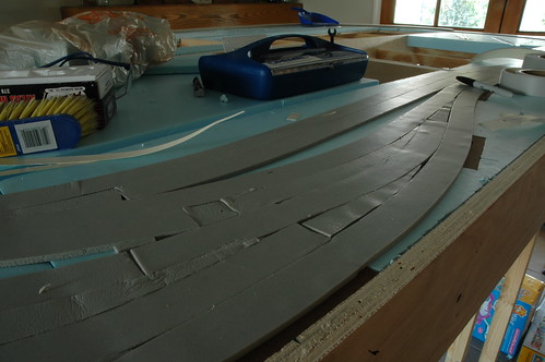
This shows the Campers tape that I am using for a sub-roadbed as shown in the Model Railroader how to book “How to Build Realistic Reliable Track”
These last two pictures shows the final roadbed product using h
This weekend I started to install the switch machines on my layout. Half of my layout has 2" of foam for my tabletop and I found this method online for installing tortoise switch machines. So as I was working I made this video (http://www.youtube.com/watch?v=d87H-zF7wXg) of how I did it. Hope you enjoy.
Campers tape is now down on the entire layout. I finished installing the switch machines last night and the campers tape today.
Above you can see one of the places that I just finished.
Now on to the Homabed, but that will have to wait till next weekend because the wife and I are off for an overnight at Catalina Island which is located off the coast of California.
The last of my Homabed arrived and I was able to complete the last of the roadbed. The last section of roadbed is now down.
Now it is time to start laying track. I am using the 8’6" ties strips from Central Valley and Micro Engineering code 83 unweathered rail. All switches are built by me using my fast tracks jigs.
Above is the first portion of my layout with track on it. You can see the first installed turnout in the upper right of the photo. My plan is to build track between the turnouts as I make and install them.
I plan on making a step-by-step on how I am installing my track soon.
I wanted to put together a post about how I went about laying my Central Valley tie strips with code 83 Rail.
First thing I did was is to make sure the area is clean:
Next run a line on acrylic adhesive down:
Then using a puddy knife, I smooth out across the entire top of the roadbed:
This is what it looks like when I was done:
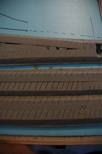
Then I started laying the tie strips:
I used thumb tacks to hold the tie strips in place when drying, here is what it looks like when I walked away to let it dry:
For laying the code 83 rail, first thing I do is make sure that the tie underneath the rail jointer is cut to ensure the rail does not lift due to the extra with of the jointer, you can see where I cut the ties here:
I have been using the contact cement that comes with the fast-track turnout kit to also glue the rail down to the tie strips. This is not needed but I know that this layout will be moving this summer and I want to ensure that nothing will come loose. After the cement has dried enough to just be tacky I lay the track down:
Final I bend over the molded on ties over to hold down the rail while the glue is drying:
Time to play some catch-up. Over the last few months I have moved from Lancaster, CA to Warner Robins, GA. This was the first move of the layout and it worked out great. Now we bought a house and the layout is up and ready to work on. Before I go into that, I wanted to talk about some of the things I was able to work on before the move.
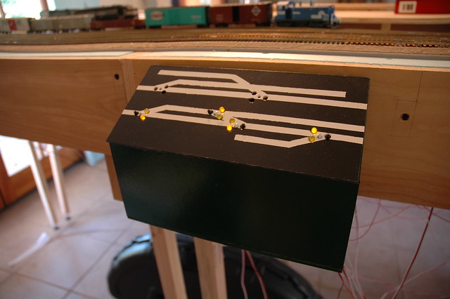
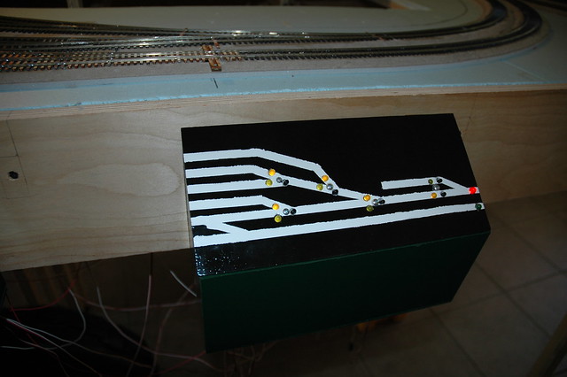
I wanted to show the off the three control panels. The control panels were all made from hardboard cut to the desired shape and size, glued, then painted. To give it a CTC panel feel the base is painted forest green and the top is black with white lines depicted the track layout. This stick drawing was actually done by first painted the top white, masking off the lines then painting over it in black. After a couple of coats the tape was removed to give it the look you see below.
The first two, the one shown above and below, were created for the side of the layout with the yard. The panel above was for the mainline and the branch that will be located in this area. The one below is for controling the turnouts in the yard. All switches are servo controlled with hardware from Tam Valley. The cool think about the panel below is that it shows the indication for the yard lead switch which is actually controlled by the panel on the other side of the layout, or since all the turnout are connected to DCC, can be controlled with the throttle.
I promised to fill you in on how I packed the layout to move across the country.
First off is the layout was designed to be movable, but not necessarily portable. What I mean by that is the layout was design to move but it is not easy. I have done some Free-mo modules in the past and the point of any modules is that you can take it to and from the site that the meeting is held. This layout is designed to broken into sections, but the sections are 3’x5’ and require two people to move them. So they can move with me when the Air Force decides to move me every 4 years but I will not be breaking this thing down to take to conventions any time soon.
The nice thing about moving with the Air Force is that they will provide a moving company to move you things from location to location. So not having to worry about how to get them across the county i could focus on how to make sure they made it in one piece.
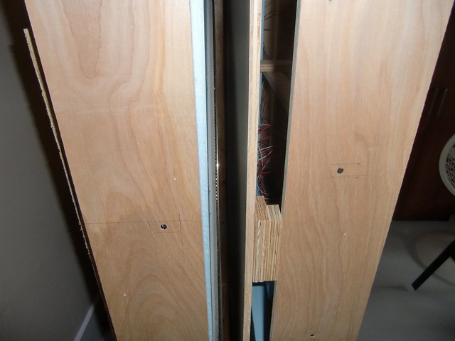
My idea was to make two boxes out of the four layout sections, by putting the tops of two layout facing each other I knew that the track would be protected. These two boxes then needed to be protected on all exposed sides to ensure the movers couldn’t damage anything.
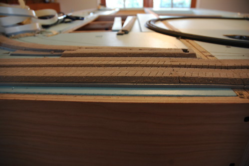
I wanted to make sure that all sides were protected, to do this I cut strips of 1/2" plywood into widths of 16". This width was calculated by how close I could get the two sections together with some between tracks. Look below to see an example on the gap between the sections
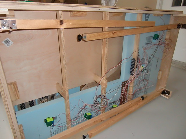
My other big concern was the underside of the layout which has all the wires and switch machines. You can see all of those things below.