I would like to wire some 12v LEDs for buildings and 6v for street lights, etc. I plan on having two transformers 1) for 12 v and 1) for 6v. The LEDs already have resistors installed on them. I have a few basic wiring questions i was hoping to get help with.
Is a terminal strip a “series” or “parellel” connection?
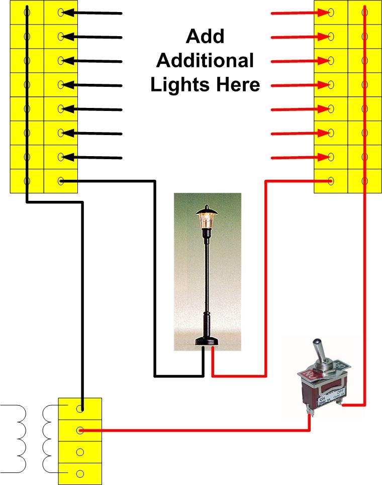
Can i use a terminal strip to feed a bunch of LED house lights instead of soldering connections? Is this a good idea?
What gauge wire do you typically use as your Bus wire for lighting? i know the feeder can be pretty small like 20 guage but was not sure about the main wire.
i am confused about AC vs. DC. i know that the track/trains are on DC but how do i know if my lighting and other accessories are AC or DC?
And it may die. LEDs are not designed to withstand high reverse voltages. Depending on the LED and other factors in the circuit, you can often get away with not having reverse voltage protection, but it’s not good practice and will sometimes lead to premature LED failure.
They won’t die if you hook them up backwards, as long as you have the proper resistors installed. They just won;t light up. Then you cna flip them around and they work.
A series connection is when several components are in a line together and the ends of the line are connected to the different poles of the circuit. The components might be lights, these would reduce the voltave with each lamp, or it could be batteries which would increase the voltage with each battery. New York City Transit mounts five 120 volt bulbs in series on a stick and connects one end to ground and the other end to the 600 volt third rail. Let there be light!
A parallel circuit places the components between the two wires like a ladder, each component connected to each leg of the circuit.
A terminal strip is neither serises nor parallel. It is just a bunch of connections. You can wire them anyway you please.
Yes, you can use such a barrier strip, but the LION does not do this. It is a waste of money (according to the LION) who solders thing directly to the bus circuit. LION is much more comfortable with a soldering iron than with a screw driver : screws are expensive, and screwdrivers play havoc with arthritis and cramps in the wrists and fingers.
LION uses 14 gauge wire throughout for all beeses. Him has lots of it on haand, and in the way that him uses wire, it is easier than the finer stuff. Bus wire should be bare (for easier soldering, of course) and to make it so, him clamps one end in a vice and cuts the insulation off with a sharp knife. Him staples the bus wires in place so they run no risk of contacting one and other.
Randy is correct and in fact this is why they are great for directional lighting in locos. They light up only when going in one direction because the polarity changes.
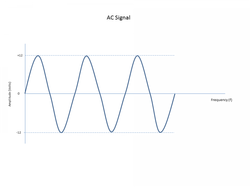
LED’s will work in AC as well. They act as a halfwave recifier. Technically they are on half the time and off half the time. For example, if you have a 60Hz AC. it will only use either the positive side or negative side depending on which way it is wired.
Below is what an AC Signal looks like.
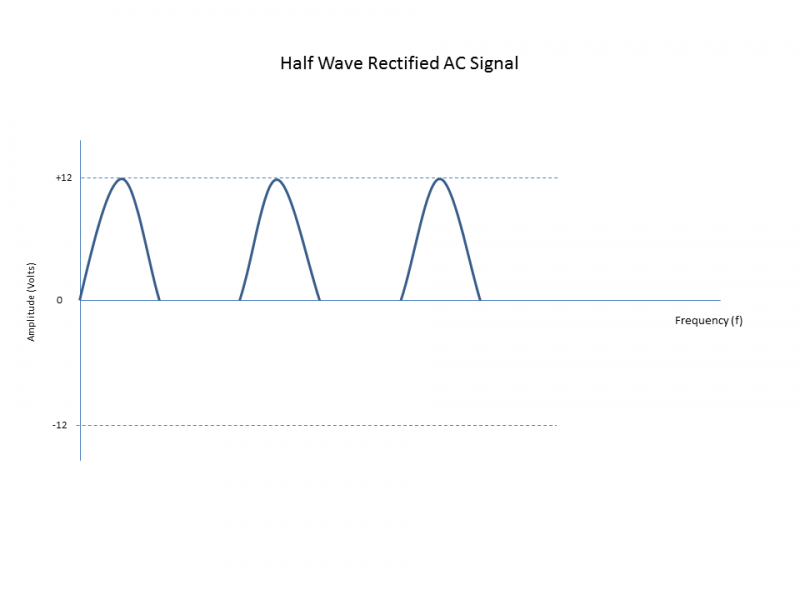
Below is what an LED’s does with the AC signal it receives. It only uses half of the signal essentially making it a DC signal. A capacitor can be use to fill in between the peaks to make a more DC like signal which is what most wall warts do. This is not a truely pure DC signal and ends up being very noisy.
It’s true that if you momentarily hookup an LED to reverse voltage, it most likely will not kill it. It is also true that you can often get away with applying AC or repeatedly applying reverse DC voltage to an LED; however, the fact of the matter is typical LEDs are not designed to operate that way and you can kill or drastically reduce the life of them doing it(even with a “proper” resistor in place).
Because LEDs are diodes, many people think you can use them like standard rectifier diodes, but LEDs do not have the high breakdown voltage of rectifier diodes. A 1n4004 has a reverse breakdown voltage of 400 volts, while many LEDs list a reverse breakdown voltage of only 5 volts. The 5 volts, however, can be missleading, because it seems to be a standard that many list instead of atually listing the measured breakdown voltage, so many may actually have a higher voltage, but I would not count on that in my circuit design.
One thing about exposing an LED to too high of a reverse voltage is they usually do not die immediately, but instead experience degradation and shortened life, so you may be damaging it and not even know it(until you have to replace the LED way before it’s time). Again, you usually can get away with it, but personally, in any circuit where an LED may be repeatedly exposed to reverse voltages I would never design the circuit without protecting the LED from the reverse voltage. First, it’s just not good design, and second, I don’t want to have to replace the LED if it dies or goes dim before it should.
A good example of this is someone who was using a white LED for directional lighting, but he only had one LED because it was an F-unit. When you have an LED for each direction, the lit LED protects the other one from the reverse voltage. When he woul test it, it would work fine, but in operation he kept blowing LEDs. Someone suggested he use a rectifier diode to protect the LED from reverse volatges and he didn’t have anymore prob