I’d like to comment on the book, and I also have a question the book has spawned.
I am sure that this book will become an instant classic, and be revered in the future as a must-read, milepost scholarly work on steam. It’s an epic accomplishment, no doubt, and a great addition to my library and probably yours, too.
But although I am enjoying it thoroughly, I must confess that quite a bit of it is Greek to me, as they say. There are many references to engineering and physics concepts that I just don’t grasp. I am not a technical guy, and this is a technical book. I knew that going in, but it is much more technical in parts than I was expecting. (There is an entire chapter solely on the subject of counter-balancing driver wheels!) I would say that if you have an engineering or physics background, OR if you are a person who is technically-minded, OR if you are a person who is simply something of an expert on steam locomotives already, you won’t have any problems.
However, if you are more like me, who is drawn more to the human and operations side, and the romance and “poetry” of railroading, you too might be left scratching your head at times.
I expected more of an introduction to how steam locomotives work, for the lay reader, and that isn’t there to any real extent. So I have now ordered this book:
The two you’re familiar with are still there, on the outside, and now we add a third, right in the middle between the frames. It works on a crank let into the main driver axle (there are pictures in the Tornado repair thread, among many others available).
Instead of the cranks being ‘quartered’ (set at 90 degrees or a right angle relative to each other) as on a standard double-acting two-cylinder engine, the three-cylinder engine sets the outside cranks and the inside crank at 120 degrees to each other (or effectively so, as the third cylinder is often raised slightly above the ‘line’ of the other two, for clearance) which promises to give more even torque (google “Swiss Drive” for some of the mechanics)
England had numerous *four-*cylinder locomotives … inside the strictures of the British loading gage! – and here you have two cylinders inside the frame and two outside. A compound version of this is the de Glehn-du Bousquet arrangement, where the LP cylinders usually rode forward (driving on the leading coupled axle) and the HP cylinders were further back, out to the sides, driving on the second driver pair.
In case this doesn’t make your head hurt enough, there were tandem compounds (ATSF was notorious for them) which put the HP and LP on a common piston rod to a typical outside-rod arrangement – even when designed for reasonable maintenance (a few of the ATSF engines actually had provision for a crane to lift cylinders up and swing them out at maintenance time!) You can imagine the augment effects from this sort of thing.
American compounds could do some weird things. Look at examples of the first kind of Vauclain compound, where the HP was coaxial with the LP on each side, one over the other, with the piston rods driving on a common crosshead. (Usually the HP was on top, but this could be inverted for more ground clearance). The fastest locomotive in the w
Do NOT get into the lazy railfan habit of saying compounds ‘use the steam twice’. What they do is expand the steam in multiple stages, and thereby get the most expansive mechanical power out of the heat contained in the steam.
Instead of the usual ‘optimization’ of a simple engine, where admission is as close to boiler pressure as you can cost-effectively make it and exhaust is at as low a back pressure as you can get while making adequate draft, the compound picks a high admission and intermediate-exhaust pressure; the power from the HP cylinders is calculated and then produced as occurring over this stated pressure difference.
That means that the exhaust steam, gathered and ‘flow-smoothed’ somewhat via a receiver, is available as ‘supply’ (just as it would be from a lower-pressure boiler directly) at that admission pressure in the LP cylinders. These normally exhaust to atmosphere with the usual considerations about back pressure and condensation, and the usual ghastly saturated-steam inefficiencies that characterized pre-superheater operation. Some people tried to reheat the intermediate steam, to introduce some ‘resuperheat’ into the LP steam to match the effect of regular superheat on the HP steam. This generally didn’t work too well. (N&W probably came closest in this country, with an arrangement that used live steam to reheat the HP exhaust very slightly (I think on the order of about 5 degrees of effective superheat) to cut some of the losses in the LP cylinders as well as providing some pressure boost.) See the Chapelon 160 A1 boiler for perhaps the best place to put an IP reheat arrangement, and proportion it.
You could, with money enough and time, do multiple expansion on a locomotive. The last of the D&H compound drag locomotives was this: triple-expansion from something around 450psi throttle pressure, four cylinders (at the corners of the driver whee
A crank in the axle, and a cyinder hidden underneath the smokebox! Why didn’t I think of that? [:O]
I believe there is an illustration in the book of a Glehn-design loco with the LP clylinders aft, behind the drivers, with the main rod extending forward to one wheel set, and the HP cylinders in the normal spot forward, connected to a different set. And I think that engine was not articulated, maybe only had 4-6 drivers total. I don’t have the book right here.
One really cool engine shown is a 2-8-8-8-2 with the aft set of drivers under the tender!
Thank you LithoniaOperator for the book recommendation and Overmod’s thorough explanation.
The LMS Coronation Class is one of the examples of the 4 cylinder steam engine, which was the most powerful streamlined engine in the UK at the time. This class had only 40,000 lbf tractive effort, which was 11.15% less than the PRR K4s.
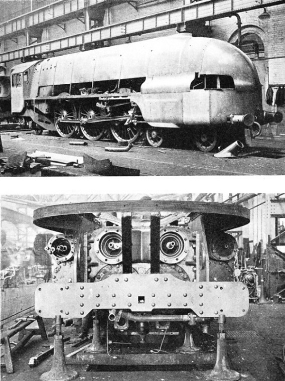
Thanks so much, Jones1945. That’s all quite interesting. I’ve learned a lot today. That final photo confirms my suspicion that there probably were no rods to other drivers. Two more cranks would be required, I would think, for balance, and that sure would get tight in there. Although I guess if you offset the middle cylinder and its main rod a bit, then you could use one only one side rod and achieve balance. ??? I wonder if that was ever tried. I can’t tell if UP 9000 has a “middle side” rod, but I am guessing not. The middle cylinder is indirectly connected to other drivers already, via the normal side rods. Was that engine actually ever built, or was it just a an idea?
UP 9000 was built all right, the first of a series of three-cylinder 4-12-2’s the Union Pacific purchased from ALCO. In the 1920’s ALCO was very enthusiastic about three cylinder locomotives and pushed them hard, but most, if not all railroads were less than enthusiastic about them, to say the least. The UP 9000’s were the most successful American adaptation of the three cylinder concept, but in the end the UP didn’t bother with any more three cylinder engines.
UP 9000 survives today in the county park that UP 4014 was removed from.
Ah, the D&H 1403, named L.F. Loree as one of the subjects in the last installment of “Consolidations, Inc” which appeared in the June 1967 issue of Trains. Also famous for being the only steam locomotive built in 1933. High pressure cylinder was under one side of the cab, medium pressure was under other side of the cab and the two low pressure cylinders were up front.
Boiler ws rated for 500psi, along with the 1402, with 400psi on the 1401 and 350psi on the 1400. Not sure what the 1403 was capable when “steam was used extensively”, but the 1402 was held back by a merchandise train while climbing a hill, while the 1402 was hauling a coal drag.
With regards to the book, my copy should arrive Saturday and am looking forward to it.
It turns out that my above “remembered” (not) description of a locomotive pictured in the book was really a conflation of two or three engines, and not a Glehl design . . .
Sorry. The jury will disregard that remark.
BUT, there are lots and lots of photos and illustrations of really fascinating engines. Great book.
Unfortunately, I just don’t have a good enough eye for such drawings that I’m sure I can discern that. By looking at photos elsewhere, I can see that the outer (regular) main rods connect to the third set of drivers; so you are saying that the middle main rod connects to the second set, right?
Are there “side rods” in the middle that connect other axles to that second one?
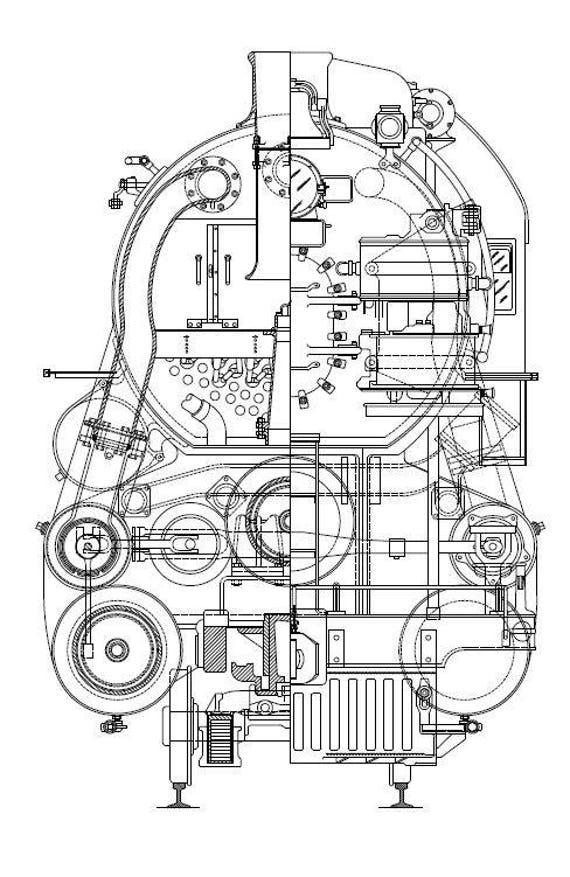
One thing that strikes me, from the front-view blueprint earlier in this thread, is how high the middle cylinder is. That surprised me. In the drawing above, I think I can see a rod coming down at the correct angle, but I lose it once we get to the front of the first driver. But I think I may see the crank and pin (if those are the right terms) on the second axle, in dotted lines, with the connection-point facing to about 10:00 o’clock. Is that correct?
If you can find a copy of Fryer’s book on experimental British steam, he goes in some detail into the question of ‘motor tenders’. The Triplexes (and Henderson’s proposed ‘too many legs and not enough steam’ Quadruplexes and Quintruplexes actually fall in this category (as do the Southern’s experiments) – if you think of them as ‘tenders with a steam-locomotive’s engine underneath’ instead of a long chassis carrying coal and water on its rear part (as in, for example, a Beyer-Garratt) you will understand what’s going on a bit better.
The situation is a bit complicated on the ‘built’ Triplexes because of the (frankly, rather sensibly derived) arrangement of compounding. Ideally a given high-pressure cylinder (at reasonable American boiler pressure) “wants” to feed somewhere between 2.3 and 2.7 times the low-pressure cylinder volume to equalize contribution to tractive effort. The Triplexes had all common-diameter cylinders, with one HP feeding the compound cylinders ‘in front’ and the other the cylinders on the tender engine. Only the residual exhaust pressure on the forward engine contributed to draft (!), the LP tender engine exhausting through an escape-pipe at the rear (there are reasons why it was not blown down to heat the tender water, as you might think would be a good use of that otherwise-‘wasted’ heat and water mass).
Strangely, lack of draft on the fire does not seem to have been an issue with them; operation at necessary long cutoff with inadequate boiler size was the real problem. A major issue was that, in this era, the contribution of radiant heating to boiler effectiveness wasn’t that well-realized (the theory still being more that the water around the firespace was ‘renewable insulation’ and the steam mostly genera
On almost all multiple-cylinder locomotives, the inside cylinder(s) only connected to ONE driver pair. A range of good reasons accounts for this, starting with recognition that even one crank in a driver axle may significantly weaken it (or require very stout additional structure). In general, American practice went toward keeping rod bearings outside where they could be easily inspected, and this is one reason why the late American four-cylinder locomotives, in the era that divided-drive began to become essential for high-power reciprocating locomotives, were duplexes (and standard 90-degree quartered DA duplexes without inside cylinders, at that!)
I think it has been noted that you do NOT have to have all three or four cranks on one axle; the de Glehn-du Bousquet locomotives, one of the most successful approaches to compounding in the world, specifically divided the drive with the inside cylinders driving on the lead coupled axle and the outside ones on the second. (There is no formal reason why a locomotive needing to preserve good rod angularity couldn’t divide the drive between the first and third axle, or even the second and third, the idea being to minimize weakening or other compromise of working strength while preserving adequate access for maintenance)
You wouldn’t get an inside rod ‘forward’ from a cranked axle without at least one other crank throw, and a matching offset crank on the leading axle(s). It makes far more sense to increase the strength of the side rods slightly to take the additional thrust of the third cylinder, which is the method used on the UP Nines (and the Baldwin 60000 ‘compound equivalent’ 4-10-2 preserved in Philadelphia) and by far the preferred solution in the post-1928 era of lightweight and stronger rod materials and fabri
Something that has not been brought up explicitly with respect to these multiple-cylinder engines – but that ought to be – is the arrangement of valve gear to run those internal cylinders. We have just had an interesting failure involving one such, on the replica British locomotive Tornado.
Note in the above pictures of the Nine there is no room for inside valve gear to work the center cylinder’s valve ‘from the rear’. What’s used instead is Gresley’s adaptation of Holcroft’s ‘conjugated’ valve gear, which uses a combination of levers to derive valve motion from the two ‘conventional’ gears on both sides of the engine. There are some practical issues with doing this and maintaining it long-term, but it should be recognized and remembered that the official world-record speed was reached on a locomotive using this arrangement.
Later, some Nines used an alternative arrangement which was a full third set of valve gear mounted behind the regular arrangement on one side, with a long rod and crank arrangement to reach the center-cylinder valve location. You can get some idea of the maintenance issues with the Gresley gear from the UP having adopted this somewhat extreme expedient. Other locomotives, notably in Poland, use the same general approach.
Note the conjugated valve-drive arrangement in the YouTube clip for the four-cylinder locomotive in Jones1945’s post. This is technically simpler in not requiring the 2:1 lever-in-a-lever arrangement.
Australians came up with what they perceived as a nifty way to get around the whip and bearing-wear issues with Gresley timing: they modified the geometry to work with shafts in torsion. All would have been well if they had used shafts that were adequate in torque stiffness… fo
Something that has not been brought up explicitly with respect to these multiple-cylinder engines – but that ought to be – is the arrangement of valve gear to run those internal cylinders. We have just had an interesting failure involving one such, on the replica British locomotive Tornado.
Note in the above pictures of the Nine there is no room for inside valve gear to work the center cylinder’s valve ‘from the rear’. What’s used instead is Gresley’s adaptation of Holcroft’s ‘conjugated’ valve gear, which uses a combination of levers to derive valve motion from the two ‘conventional’ gears on both sides of the engine. There are some practical issues with doing this and maintaining it long-term, but it should be recognized and remembered that the official world-record speed was reached on a locomotive using this arrangement.
Later, some Nines used an alternative arrangement which was a full third set of valve gear mounted behind the regular arrangement on one side, with a long rod and crank arrangement to reach the center-cylinder valve location. You can get some idea of the maintenance issues with the Gresley gear from the UP having adopted this somewhat
My copy arrived in the mail today, been too busy reading to do much posting.
Update: It’s a good read, and brings back memories of my earliest reading about steam locomotives, particularly the June 1967 article on the D&H high pressure compaounds and the June(?) 1968 article on the “Big Engines”, with Withuhn’s book explaining the math behind the '68 article. One interesting tibbit was learning that D&H 1403 was credited with a 10.5 to 12% thermal efficiency.
The chapter on the T-1 and poppet valves may toke the fires about the T-1’s top speed. Withuhn states that Franklin was wondering why the poppet valves were breaking on the T-1’s, when a similar installation was rock solid on the K-4. He went on to state that the valves were breaking on a specific division, so they had a “mystery rider” on the trains with a stopwatch to time the milemarkers. The reports were that trains were often exceeding 120mph and on rare occasion would approach 140mph.