BLI 2-8-0 HO Paragon 4:Wire designation from tender to engine.
What are the wirer’s designation from the tender’s female plug left to right? Or looking at the male plug-in on the loco from left to right?
Anthony
BLI 2-8-0 HO Paragon 4:Wire designation from tender to engine.
What are the wirer’s designation from the tender’s female plug left to right? Or looking at the male plug-in on the loco from left to right?
Anthony
Hello, Anthony
My 2-8-0 (was) a Paragon 3 and I recently gutted the BLI electronics and replaced it with a Tsunami2 and even managed to squeeze in a keep alive capacitor in the small PRR Lines West tender.
Usually I keep pretty good notes on the wiring harness but since I was removing the “chuff sensor” and smoke maker plus other BLI electronics I was primarily concerned with rail pickup and motor wiring, which is usually consistant on BLI engines. After that I wasn’t too concerned with their somewhat unconventional wiring.
So far the only Paragon 4 engine I’ve gutted was the streamlined K4. When I got inside that I discovered that BLI had gone to a different wiring of the LEDs using a common cathode arrangement.
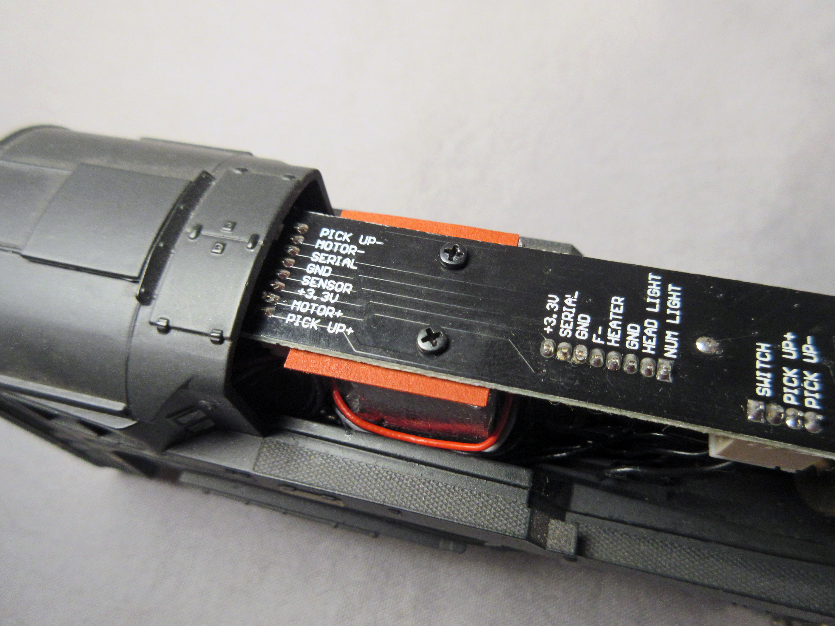
Recently I started on one of my T1s and found, surprisingly, that the PC board was pretty well marked with the component assignments. I show this as reference for you:
 BLI_P3_T1 by Edmund, on Flickr
The arrangement shown is pretty typical for BLI however I have found some with the motor + and — reversed. “Usually” the 3.3V+ which would commonly represent the lighting blue wire on a typical DCC NMRA decoder is in the same spot and the “sensor” as well.
BLI has been getting more “sophisticated” with their lighting so it seems they are using that “serial” signal to trigger the headlight dimming and the cab light coming on when movement stops. Some smoke unit commands are also carried in that serial circuit as well. There is a “control board” in the boiler that decodes this signal and assigns various functions to lights and the smoke unit.
All this might not help your particular P4 2-8-0 but give you some basic guidance.
So far the only Paragon 4 I’ve dealt wit
Ed: Thank you for helpful information. Today, I received from BLI a picture of a Paragon 4 decoder with all the outputs labled. I have spent the last 30 minutes trying to include the pic in this reply with not luck.
Anthony
I must have misunderstood.
I thought you wanted the wire assignments between the engine and tender.
This is the last version of the Paragon3-G:
 BLI_K4_cap by Edmund, on Flickr
I’ll be opening up my P4 E6 later tonight and I can get a photo of it for you if it will help.
Good Luck, Ed
Ed: Yes, I would like any pictures you have of a Paragon 4.
Anthony
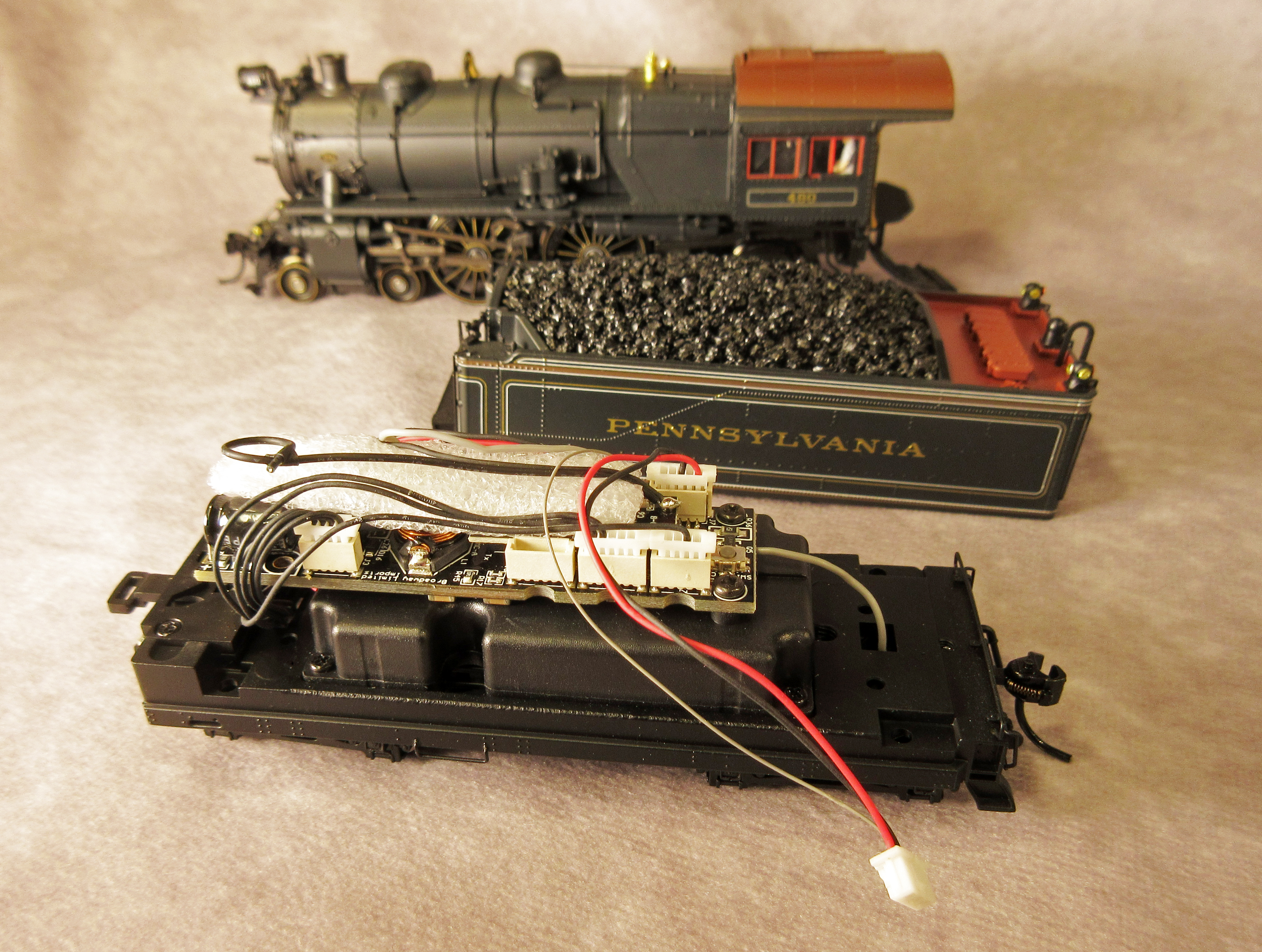
This PRR E6 Atlantic should be the latest iteration of the Paragon board.
 BLI_P4_E6_overall by Edmund, on Flickr
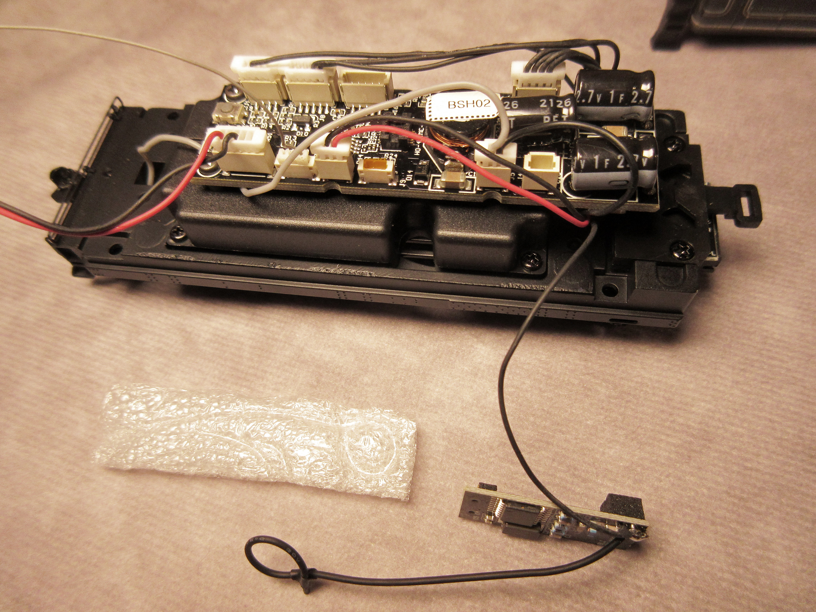
Transmitter still plugged in and foam in place:
 BLI_P4_E6_as-found by Edmund, on Flickr
Tether plug with markings legible:
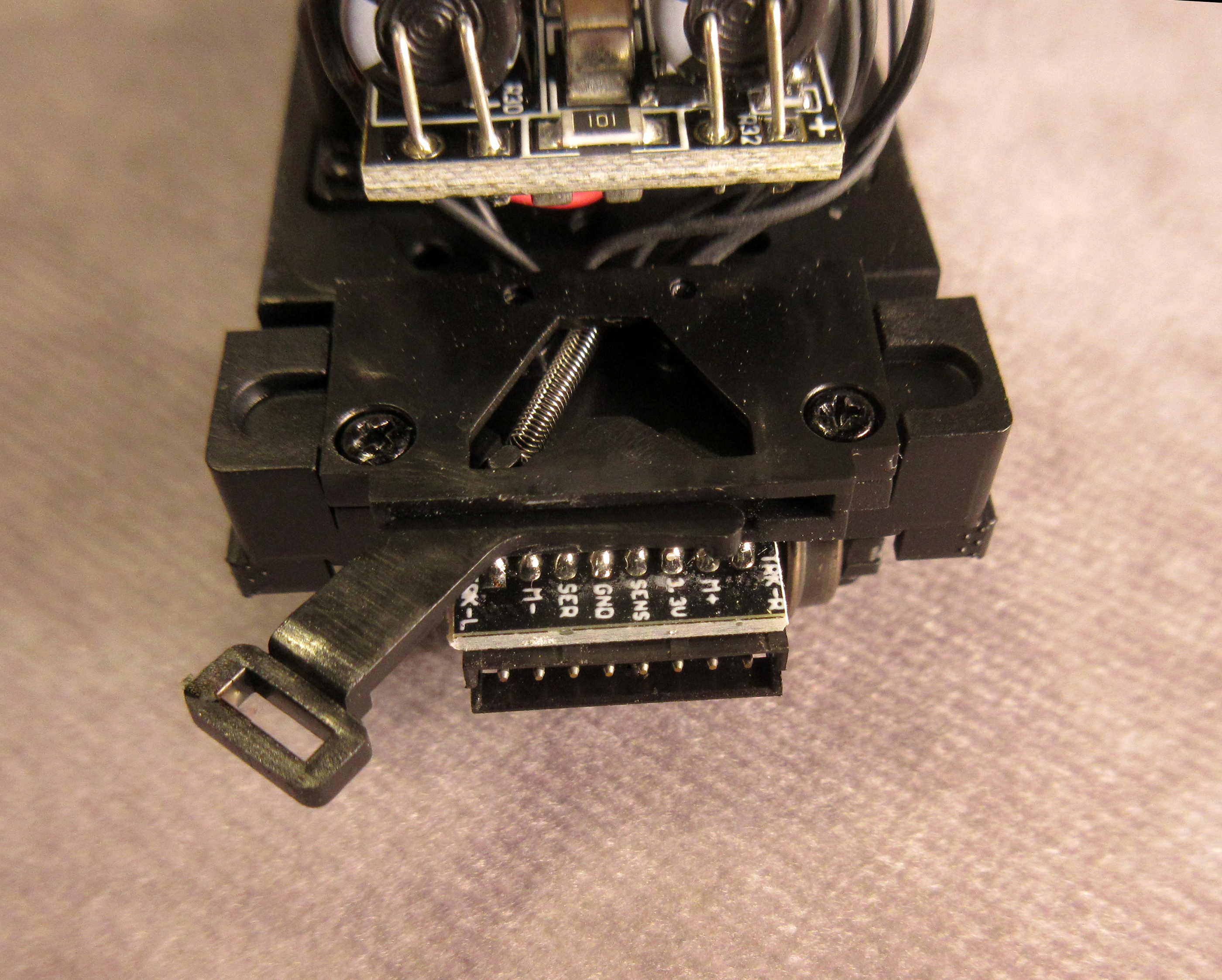 BLI_P4_E6_tether by Edmund, on Flickr
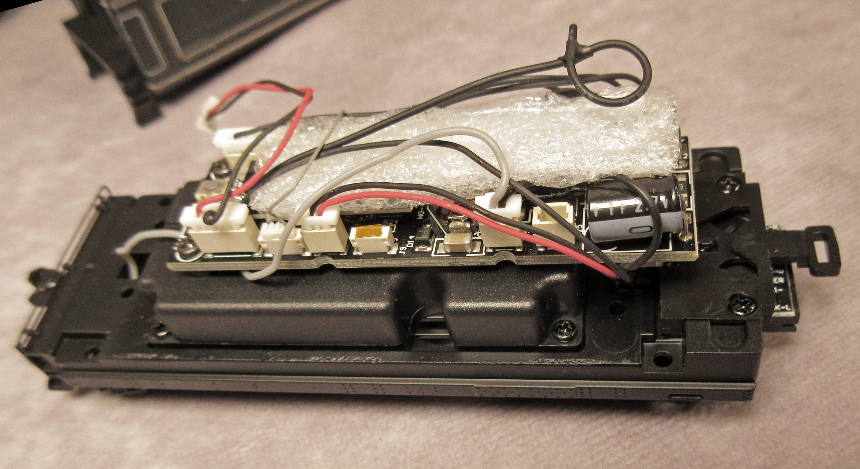
Transmitter removed. Earlier versions didn’t have the additional wire soldered to the antenna. I’d have to dig deeper to see exactly where the other end is soldered:
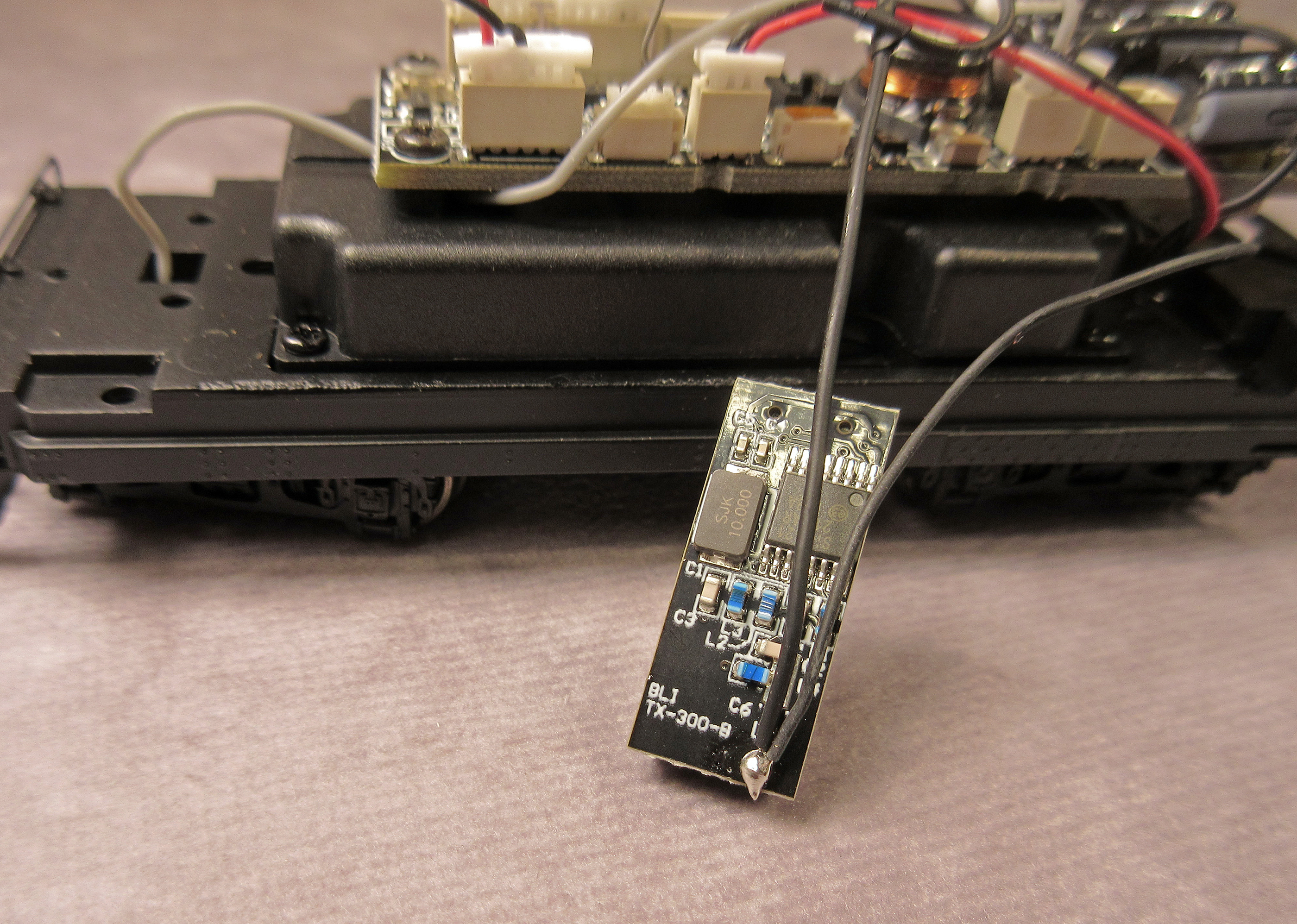 BLI_P4_E6_xmitter by Edmund, on Flickr
The right (engineer’s) side of the board. From the left (rear) Backup light + and —; gray = marker lights; red/blk = speakers; Kapton covered*; gray/black= tender wheel pickups; empty:
 BLI_P4_E6_right-plugs by Edmund, on Flickr
Left (Fireman’s side) of the board. From left (front) Engine wheel pickup and motor +/—; not used; +3.3V and serial signal (lights); Chuff sensor.
[url=https://flic.kr/p/2o51HUJ][img]https://live.staticflickr
I can say that yes, the small plug next to the speaker with nothing plugged in, on yours, is for their GoPack. P4 has a “mini” version built into their decoder now, but the plugin has “significantly” more capacity. So I still see many people install GoPack’s in their Paragon 4 anyways, even if they don’t “have” to. The other small plug between the 5 pin and 2 pin speaker is new to P4 which is for additional lighting outputs.
And the wire on the RollingThunder board, I have seen that in some Paragon 3 engines as well, generally bigger ones like the BigBoy and such, and is just an additional much longer antenna.
And that is correct, in which they use the “serial” connection to their smoke unit controller board inside the engine, to control a bit of lighting inside the engine, as it allows them to use fewer wires between engine and tender.
Ed: I have been able to trace all male pin connections on the loco to their respective wirers. I removed all the unessary stuff and only have wires remaining. I have one problem. I can not get a continuity between the 3.3V male pin and any of the wires. Any idea why this would occur. It would seem there is something in the wire that prevent current flow. I have identified left and right tracks, M+and M- , ground(-), serial and sensor. I have more wires than the 8 male pins on the connector
Anthony
As the engine is apart, are you able to see the traces on the PCB board itself for that pin? You should be able to spot them and follow the trace to see what wire it goes to.
Of course always a possibility that the solder join is not great and its “broken” at the connector, so you can’t tone anything out from the connector itself.
Hello, Anthony
I can’t quite visualise what two points you are checking for continuity. Loco or tender? I am presently “unpacking” my recent PRR E6 Atlantic and gutting it while also trying to locate a short.
This engine has been back to BLI and when returned it still shorts between the rails. BLI repair noted that they “corrected” the situation and this amounted to painting liquid “tape” on the six wires coming out of the front of the “sensor/contact” board.
Did you remove the “light/smoke” control board inside the engine? This is normally wrapped in heavy heat shrink tubing. On the E6 it was tucked under the motor.
 BLI_P4_E6_light-control by Edmund, on Flickr
I traced the wire that is soldered to the “Rolling Thunder” transmitter antenna and it IS the +3.3V wire! Why they decided to take the 3.3 from that point is beyond my comprehension. With that add-on R-T transmitter unplugged there isn’t 3.3V going to the tether harness from the decoder anymore.
The wire seen here going under the board is soldered to the +3.3V pad on the tether socket.
BLI_P4_E6_right-plugs by Edmund, on Flickr
As long as BLI insists on keeping that smoke maker and the associated “chuff sensor” their wiring woes will continue. The E6 is a compact little engine and BLI has done some marvelous work in engineering the machinery. One nice recent addition is the contact pins that eli
Ed: I am refering to the loco. The pins are marked on the board. The pin marked 3.3V is the one that I can not find a wire for. I have taken the smoke and chuff stuff out. I only have the wirers coming from the pin board left exposed infront of the motor.
Anthony
Again, I wish I would have documented the 2-8-0 better. Here’s the L1 and as I recall the +3.3 wire terminated at the board that the reed switch (chuff sensor) is mounted to.
The white plug near the gear tower shown here should have the 3.3 wire going to it:
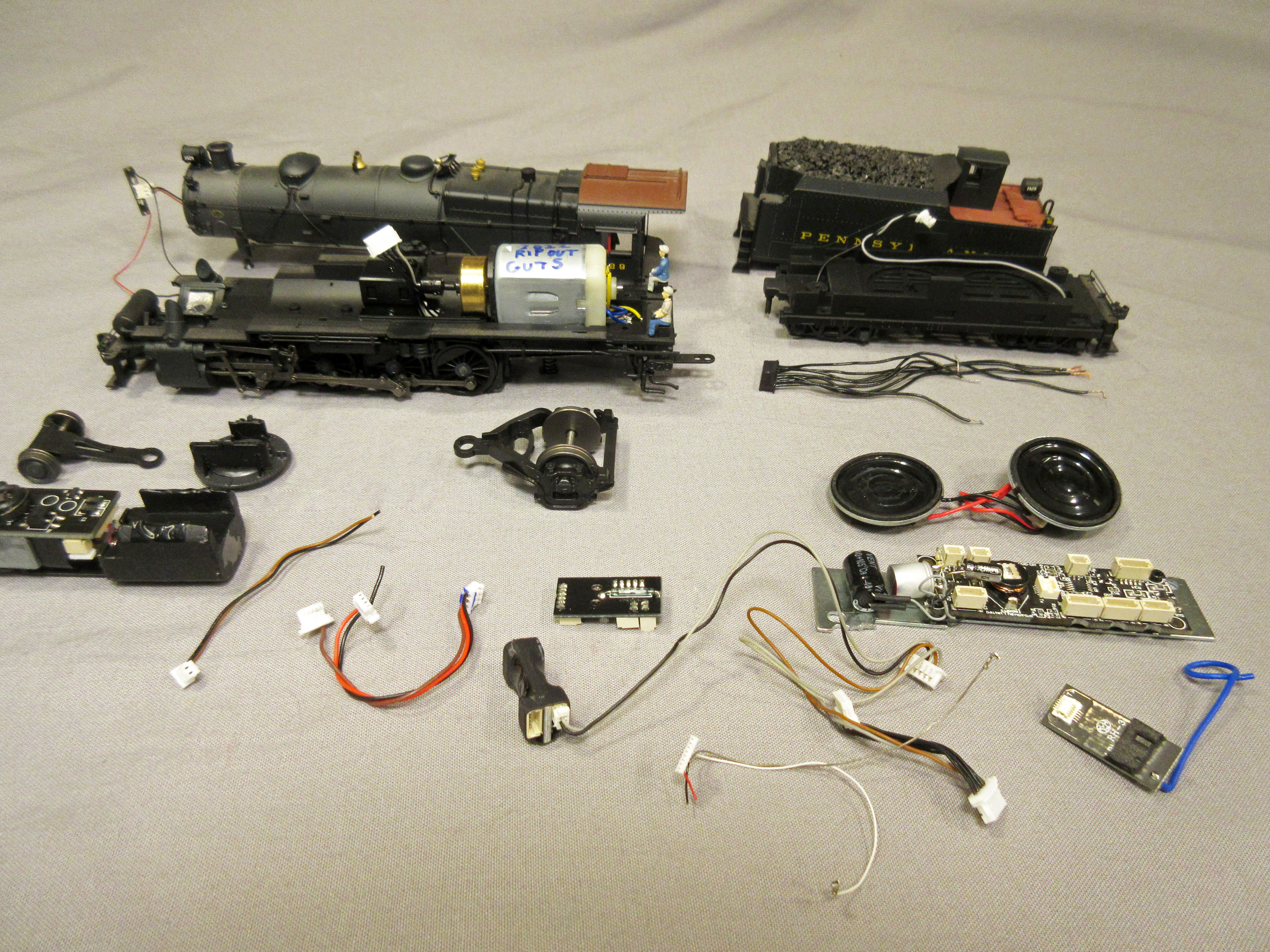 PRR_L1-BLI-guts by Edmund, on Flickr
Is it possible that the wire wasn’t adequately soldered to the pin socket and inadvertantly got disconnected?
I’ll take a better look at my 2-8-0 and see if it jogs my memory.
Good Luck, Ed
Ed: I plan to use either the sensor or serial pin for my 3.3V+ supply. Both of these are free after the removal of smoke and chuff stuff. I will wire the tether from the tender accordingly. I will be using a Soundtraxx TSU 2 for a decoder.
Anthony
Ed,
The 3.3v on it, the factory used as just a longer antenna for rolling thunder. That wire off the RollingThunder abosulty does not have +3.3v on it. On those engines, the smoke units have a regulator for 3.3v on it for power, so the decoder does not have to directly provide +3.3v to the engine.
Some engines do actually go out from a 3.3v pin on the decoder, infact most do. But some of the big engines, such as their BigBoy, as you have seen, do not take 3.3v from the decoder.
P.S
My source are the schematics for their electronics, pin-outs, etc. and also directly from their software/hardware developer, that designs their hardware, writes their code, etc.
Thanks for clearing that up. It didn’t make sense to me that voltage would be pumped back into the transmitter but the screen printing on the board labeled the terminal as +3.3V.
Prior to P4 the Rolling Thunder transmitter could simply be popped out (and left out) but recent models have that second wire added.
BLI just refuses to give up that smoke maker and, I presume, the reed switch/chuff sensor is necessary for the “puffing” signal to the tiny blower in the smoker.
Lots of excess baggage — electronically — IMHO.
Eventually ALL my Paragon decoders will be gutted and replaced with ESU, WOW or Tsunami as the case may be. There’s not one single “Goldilocks” sound decoder out there.
Regards, Ed
Well, that’s why it is more odd that you were saying that stuff stopped working when you popped it out. And I have seen that specific setup on many P3 as well, with a wire soldered to the antenna out on that board, going to the 3.3v marked connector on the tether board. Basically the engines in P4 that are setup that way, the same engines in P3 are as well. The RollingThunder board is the same as well in both P3 and P4.
Now, it’s not to say that sometimes their factory does not change how they wire things and what they do, as they had done that before, without BLI’s knowledge about it. But I believe that all has improved/stopped once BLI put someone overthere to oversee the stuff. I would just honestly need to see one myself to see what exactly is going out since it should have no impact, being removed or not, etc. and if it truly is needed, then it’s certainly not something that their engineer is aware of at all.
The reed switch is actually for all chuffing related functions. Every BLI steam engine since BlueLine has a reed switch inside, smoke or no smoke in the engine. It ties back to the decoder
Ed: How, did you remove the shell from the BLI E6 4-4-2? I just started to change the decoder in my 4-4-2 but am stopped because I am not sure how to access the engine’s internal wiring. I have removed 4 screws from the underside of the 4-4-2 but do not know what to do next.
Anthony
Check under the dome on the big boys its a screw under the cap
[quote user=“tsd”]
gmpullman
Thanks for clearing that up. It didn’t make sense to me that voltage would be pumped back into the transmitter but the screen printing on the board labeled the terminal as +3.3V.
Prior to P4 the Rolling Thunder transmitter could simply be popped out (and left out) but recent models have that second wire added.
BLI just refuses to give up that smoke maker and, I presume, the reed switch/chuff sensor is necessary for the “puffing” signal to the tiny blower in the smoker.
Lots of excess baggage — electronically — IMHO.
Eventually ALL my Paragon decoders will be gutted and replaced with ESU, WOW or Tsunami as the case may be. There’s not one single “Goldilocks” sound decoder out there.
Regards, Ed
Well, that’s why it is more odd that you were saying that stuff stopped working when you popped it out. And I have seen that specific setup on many P3 as well, with a wire soldered to the antenna out on that board, going to the 3.3v marked connector on the tether board. Basically the engines in P4 that are setup that way, the same engines in P3 are as well. The RollingThunder board is the same as well in both P3 and P4.
Now, it’s not to say that sometimes their factory does not change how they wire things and what they do, as they had done that before, without BLI’s knowledge about it. But I believe that all has improved/stopped once BLI put someone overthere to oversee the stuff. I would just honestly need to see one myself to see what exactly is going out since it should have no impact, being removed or not, etc. and if it truly is needed, then it’s certainly not something that their engineer is aware