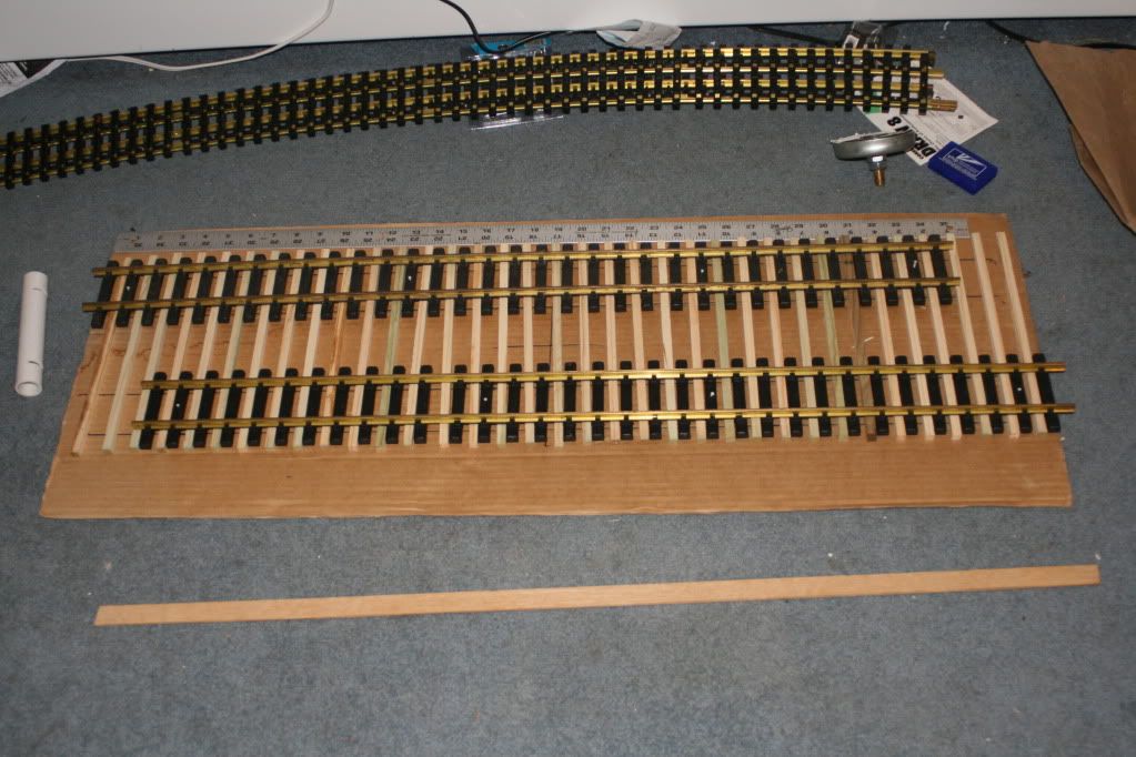
This is the basic layout of the stub cross over Switch. I needed four inches between inside rails. This is clearance needed for the Articulated engines to clear equipment on outer track.
The 3/4 PVC to the left is my 4 inch track gauge. PVC is easy to work.
I ripped the ties to the same height of the Aristo ties. This raised the track a bit higher under the Aristo. There is the under rail tie joiner holding Aristo ties together.
When I laid the rail. It is now the same height as the rest of my layout track.
I placed a touch of glue at each end of my ties. This held the ties in place to the cardboard.
Notice the CROSS in the center on the cardboard.
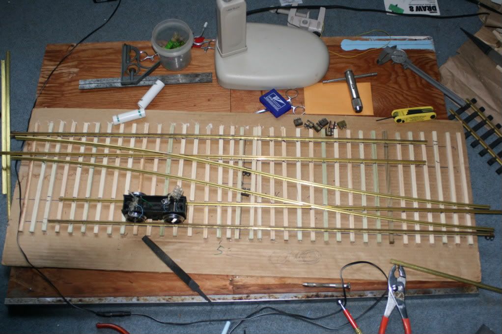
I used Aristo straight and 10 ft R track sections to plan the track layout.
I laid my convergence of the curve over the straight track.
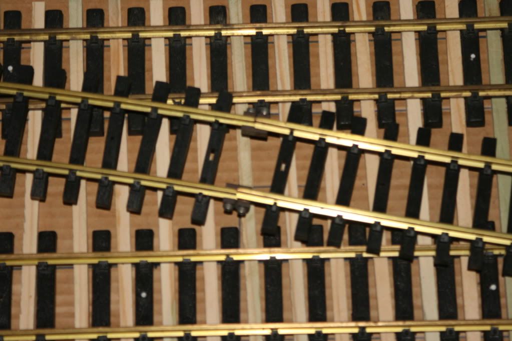
Remember that the radius of the rails changes at the center point. It changes form inside radius to outside radius.
Connecting two sections of the curve track sections gives you the correct curves.
Just remember to place the center of the track section junction over the center point. I trimmed a piece of thin wood to fit inside the section of track. I then used a nail to match the centers.
Then I adjusted the curve sections to fit in the straight track sections. I kept adjusting the track sections (both straight and curve) to match rail ends. I placed a combination square against the outside rail to place the ends.
This was all set until I was ready to cut the rails. I decided would be easer to cut the straight. I cut
Very cool switch(s) You seem to be doing a great job…it is not easy.
Mine was for live steam so i just soldered the complicated bits to a peice of brass then nailed that to the ties…no worries about short circuits.
One thing that may save some effort is that you can bend the rail sideways to make the guard rails and frog areas. I clamped the rail in a vise then just bent them by hand to the right angle…looks pretty good too!
not much can be done about the electrical connectiviety if you solder stuff…
If you kink the rail a little, perhaps you can pound it back into shape with a hammer like a blacksmith. it was probably 20 years ago I did mine I do not recall if i had the kinking problem. if you have a vise or flat cast iron saw table top use that as an anvil to smith the offending rail into shape.
I attempted to use Micro-switches to power the rails. I found 4 perfect switches in my junk box.
When I attempted to secure them with a nail. I slipped and broke to mount for the actuating arm.
I used the movings section rails to actuate the Micro. Common is picked off the moving rail. normal closed feeds the straight rails. normal open will feed the cross over rails.
I am doing this for one. When I test run the engine over the stub. I would lose power.
I also want to isolate the unused rails. When I derailed on my Aristo 10 Dia. cross-over. I shorted and fried the witing in my BIg Boy and Challenger.