I just had an idea on how I could expand my future layout project if I can provide a easy access pathway to behind my bar area without using a duckdown. I need to maintain a doorway type opening and came up with the above idea. The section would only be about 6-8" wide, enough for two lines of N scale track and roadbeds, and need to be a minimum of 24" long (for the opening) but a 32" opening might be better.
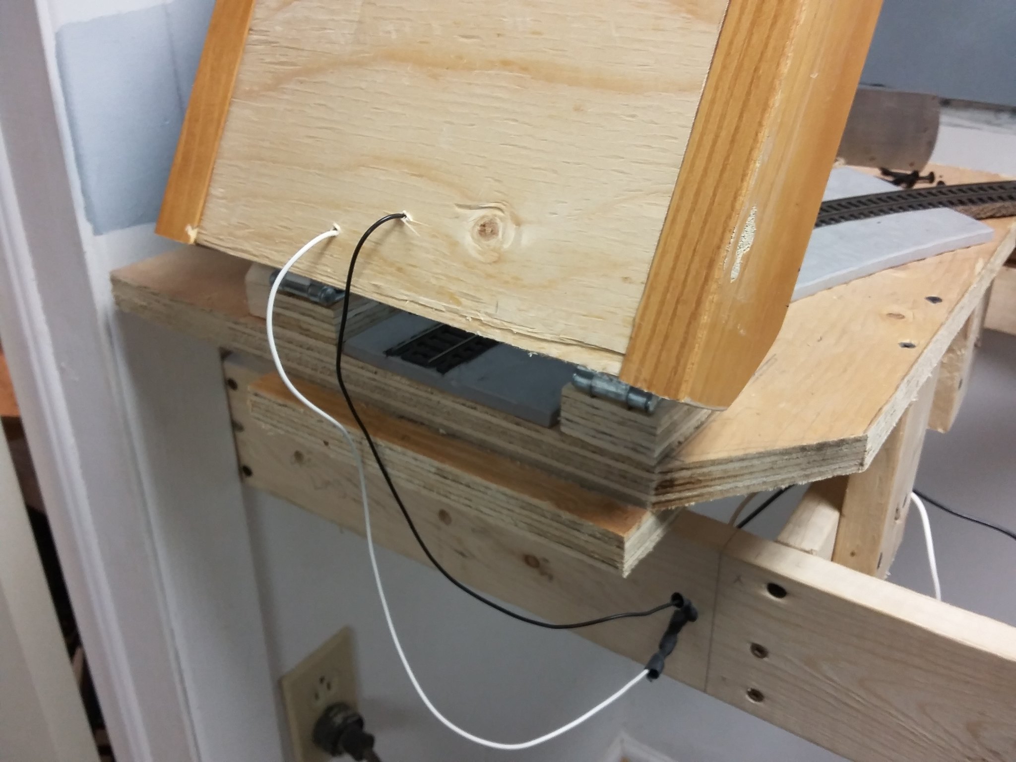
I know I would need to provide jumper wires on the hinge side to electrially connect the drop down section of track, but am wondering if there is anything else I need to consider to make this work. I am thinking I would have track on a bed of cork or something on a piece of plywood, which is then further supported by a 2x6 on its flat side.
You should consider a power kill that shuts off power for several feet on either side of the drop-down, to prevent trains from entering the gap when it is open. Of course, that’s an opportunity to add signals, too, because who doesn’t love signals?
The open side probably needs a better alignment fixture, too. Particularly in N-scale, it must line up perfectly, horizontally and vertically, every time.
I’ve made two lift up sections in my 69 years of model railroading. 1) HO 34” x 8” lift up for my first layout, an around the room shelf layout (1951). 2) G gauge Howe Truss Bridge 60” x 8” between our patio and fence with a 45° curve at each end of the bridge (2004).
I made a latch to hold the lift ups in the up position. I used ¼-20 bolts for alignment pins on both lift ups. For some reason I never felt warm and fuzzy with a drop down.
I made an electrical interlock to kill power to the approach track to prevent anything from taking the big drop to concrete, very important!! On a drop down you have to protect both tracks, only one with a lift up. I kill the power to 35’ of approach track when the bridge is up, the track is attached to a shelf on the fence leading to our garden. DO NOT TRUST YOUR MEMORY to protect your trains from the big drop!!
I was indeed thinking about the alignment aspect after posting this. I think if I use a heavy enough hinge that side will be ok, but on the open end I was thinking about maybe a wedge type dovetail effect in the boards so it starts out loose and tightens into final alignment as it closes fully.
I have some woodworking experience and even a few dovetail jigs so I should be able to come up with something. I had also thought about using pins and even the barrel bolt idea too, but the simpler the better I think.
As far as the switch to kill power on that track section when the “bridge” is up (or down) that is an awesome idea and the exact type of feedback I was hoping for, thanks for the idea guys. I do like the idea of wiring to kill power some feet away from the “bridge” as well, maybe 6 feet on either side?? Also the use of signaling is another great idea, keep 'em coming.
I’ll try mocking something up over the weeknd and see what I can come up with.
Duckunders should not be feared unless you have physical disabilities. On my old layout, I built a liftout section that housed two bascule bridges, and it spanned an aisle that led to the far end of my layout - - installed at an angle no less.
It was wired to provide track power and signal power on the lift out section. It did not require jumper plugs or other wire connectors since I had installed metal plates on the underside of both ends of the liftout that mated with metal plates on the layout itself where the ends of the liftout sat. The metal plates conducted the electricity necessary to power the liftout.
A hinged lift up is harder to construct so as to line up the tracks. Drop downs are easier. Reason is the height of the railhead above the supporting roadbed.
It’s not that I fear them, it is just there is some other equipment back there that might require a regular size opening every once in awhile.
For normal use I would probably just duck under it, but I can’t permanently block that area off. From what I am reading from you and others I might consider changing it to a lift up design, or perhaps even a drop in section.
Thanks for the feedback it gives me more options to consider.
Yeah, I might just try going the drop-in (lift out) route as then I could make a better wedge joint to align that section better. I was looking at some hinges today at the local hardware store and they all have too much lateral slop to them, so using a hinge I would need to take measures to align both sides anyway. Seems it might be a bit too much to tackle on my first attempt at building a layout.
I can mock this section up easily enough with a few peices of scap lumber and see what I can come up with, thanks for all the input.
The problem is that the ‘heaviness’ of the hinge isn’t what’s critical: the alignment is. In my experience most heavier hinges also have a little clearance play between the pin and the bores, the more precise surfaces being those that vertically support something like a heavy door panel. Neither plastic nor ball-bearing hinges are likely to give you what you want, which is long-term precision between pin and leaves – often the thrust surfaces are flat to increase effective contact surface or preserve ‘ball’ action vertically with increased pin wear or slop.
The key is to get the hinge attachment on one side – probably the fixed side? – so you can perform fine vertical and horizontal position tweaking without having to shim the hinge screws or some other disastrous death-march progressive loosening adjustment. Then if the hinge wears or stretches, or humidity makes the benchwork warp slightly, you can make adjustments to keep running trains smoothly.
You have both the right idea and the right implementing tools. But again, be sure that you have means to tweak the position and alignment of at least one side of the dovetails, as a very precise final fit is involved, perhaps finer than the slight crush that a wood-on-wood dovetail engagement might experience over time or in practice.
Think about a vertical dovetail engagement at the hinge side, too, perhaps with a vertical leveling screw on each outboard side: the heel of the board would automatically center vertic
After building my truss bridge and putting it in place with the tracks aligned I drilled four ¼” holes, two in each end, to firmly keep the track aligned. Once the bridge is lowered I push bolts through the holes. I use wingnuts on the non hinged end to keep the bridge secure. The bridge is over a walk way and I don’t want someone lifting the bridge without thinking, including me.
Moving the bridge accidently could cause a derail if not corrected causing $$$ damage to a locomotive. The bridge looking to be in place can be bad news if out of place.
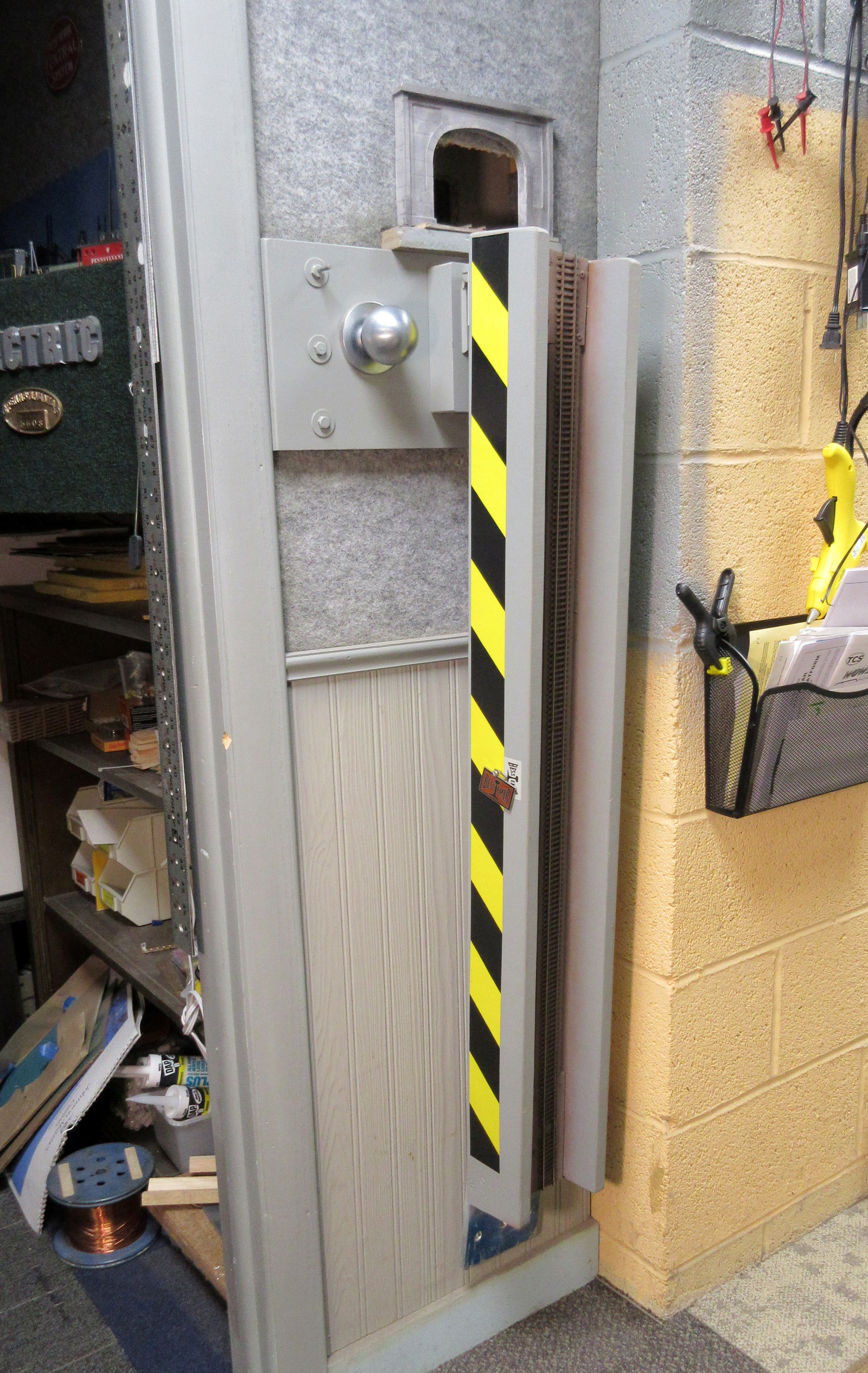
The hinge is a heavy-duty one which also has nylon inserts that take up any “slop” and mine is attached to a milled aluminum block since my bridge is “skewed” about five degrees.
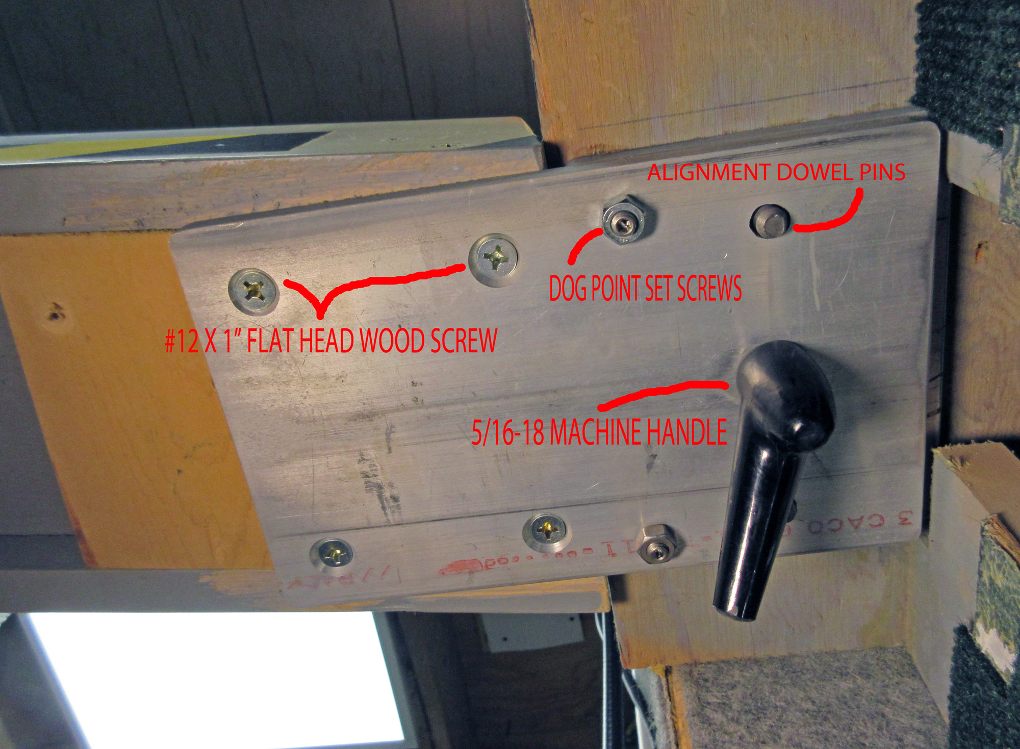
The block is anchored from behind to an oak board which is lagged into the studs of the wall. On the open-side of the bridge I used a 1/4" aluminum plate that I pressed two dowel pins into which align with the mating plate.
A stud passes through the center hole and a hand-wheel secures the bridge in place. I use a pair of dog-point set screws for any minor height adjustment but I haven’t had to adjust it, ever.
Wow, thank you so much for the pictures and details Ed. Good to know a dropdown can be done like this.
I am in the process of mocking up a few pieces of wood right now to act as a simulated bridge to test out various concepts, but your detailed response should fast track my own progress.
It looks like most of the stability in your design comes from the aluminum plate and dowel pins. I will need to explore that aspect more as I was orginally thinking of just using wood joints, but I can see how over time wood can wear down enough to potentially cause alignment problems. Seems like metal is the way to go for the critical alignment pieces.
Thinking about the metal aspect gave me a few new ideas. What if I just do the whole base of the bridge in aluminum? I looked up prices of flat stock and can get a 1/4" thick, 4’ wide and 48" long piece of aluminum flat stock for about $25. That would be enough for the base of the bridge and any plates on the ends. How wide do I need to go for 2 tracks of N scale running over it?
Then I got thinking about attaching the hinge and got wondering if I could get a hinge welded onto the flatstock. I assume there are aluminum hinges?? Any other metals compatable with welding to aluminum. I know there is a shop nearby me that does aluminum work as we had some done years ago, but I am not that knowledgeable in that dept.
Then if I did the same on the other lip of the hinge by welding it to a piece of aluminum left over and then drill holes in the plate to attach securily to my platform frame. This would take a lot of the variances out, and on the open side I could do like Ed with dowl pins, but they would go directly into the base since it is already aluminum.
Of course then I could maybe get some thin diamond plate metal and make sides out of it and make the whole think look like a bridge, probably not proto but I am not too worried about that aspect.
Just thinking out loud and wondering if anyone has already gone down that route and used all metal for a bridge whether in a drop down or not.
I only used wood for my lift-up gate. Unless you are expecting tons of visitors and a lot of wear on it, I would say it’s not absolutely necessary to build something out of aluminum. By the way, the advantage of a gate that drops into place is that it makes it easier to build braces. Gravity holds it in place, and if you use wood (and roadbed) that is the same thickness as the layout, it’s a cinch to get the right height alignment. For the sideplay, you just need to build side braces where the gate lands. As for the hinges, placing them on small blocks will allow you to get better precision when the tracks fall in place (because of the greater angle). I also put a switch that shuts off power to the tracks - on the entire layout - for safety.
I used a length of similar stuff for a lift-out on a G scale railroad once. Very strong, very stable.
They are a little flimsier but maybe look at some steel studs while you’re at it? Maybe you could add some bracing or cut a nice piece of 1/4" or so, plywood to lay inside the stud channel to stiffen it up and make a base for your track.
Most seem to be 25 ga. (flimsy) but there are others made for load-bearing walls that are heavier. Look around for 20 gauge or thicker “structural” steel studs.
Note that it is important for a drop down track section (one that drops down into place when hinged on one side) as opposed to a lift up (meaning a track section that lifts up into place) that the pivot point for the panel that drops down into place be above the top of railhead. The photos on the above post show that. It doesn’t have to be by much but it does need to rotate in such a manner that the railheads separate as soon as the lifting begins. Panels that drop down to provide access are somewhat easier to align because the rail heads automatically separate right away.
Sorry, the OP described his plan as a drop down, meaning drop down for access rather than drop down into ready to run position. Then a useful set of photos showed a lift up section that “dropped down” into the ready to run position. The geometry of these two methods is very different because of the need to allow for the height of the railhead when hinged so as to lift up out of the desired passage.
Somewhere recently a poster put up a photo of a lift out panel that used wedge shaped alignment. That appeared to be simpler and far more reliable than any hinged arrangement.
Here it is, from doctorwayne, very fine modeller with very good ideas:
You will have to copy and paste the link into your browser because I cannot get these links to paste with the active character.
Not a wedging action, just precision cutting and alignment. Do it right first time and enjoy forever. You could add a wedging shape for self centering and even add some catches. Don’t overlook those strong rare earth magnets (Lee Valley tools are big fans of these as affixing points) to hold the drop in/lift out in place. Fit the magnets to the base table to avoid accidentally picking up metal bits from wherever you might put the lift out for some reason.
You have this worded backward. The pivot for a lift-up is the one that goes ‘above’ the railhead; if you do this for a drop you’ll need significant undercutting or ‘scissors’ clearance. Whereas a simple barrel hinge gives all the railhead separation action you could want…
Fix the language and sense, and I’ll delete this post afterward.
Hmm, yes, read one way rather than as I intended. Thanks for that heads up. It did not occur to me that the description might be ambiguous.
I meant drop down into place rather than drop down out of place. Like “lift out” which was probably what I was thinking of. Let me try and clarify what I thought was clear. Have a look at my edits and see if that works.
I recommend you leave your post in place anyway. That way, anyone reading the thread will be alerted to the two differing ways to express the same thing. Is “normal” the position described when the track is closed and ready to run, or is the normal position when the section is in the open track position? Which situation is being described when you use "lift up"and “drop down”?
For duckunders the reference is of course always to the track in place ready to run being as “normal”. For “lift outs” the reference is to not normal track condition. For “drop in” one thinks of the track being ready to use when “dropped in”.