We decided recently to hide the hole in the wall leading to the staging with an elevated highway on the club layout. I’ve been working on it for 3 evenings in a row…
It was made out of 1/4" MDF (masonite) board, sheet styrene (.5 and 1.5mm) and plastic sprues and wire for the drain. The pattern on the guardrail was made by laminating pieces of .5 styrene. Paint is Krylon satin finish. It is a good warm concrete color and should looks nice once lightly weathered.
Missing on the pictures are the street lights and railings (probably with Plastruct tubing).
The prototype is Dufferin-Montmorency Highway built in 1976 and located in Quebec City. However, the design of this structure goes back to 1957 which is the year we model.
Very impressive. I’m always trying to find a model kit for everything and it just goes to show that you can build most protypical structures out of basic materials. We’ll, having some building talent helps too. Thanks for sharing.
I scratchbuilt the railing this afternoon from .5 and 1.5mm sheet styrene. At first, I thought about using Plastruct square hollow structural shape but the remaining local hobby shop asked 13$ for it and I just needed about 3 inches long. So I made my own structural shape and cut it at lenght. Not the easiest way, but a lot cheaper.
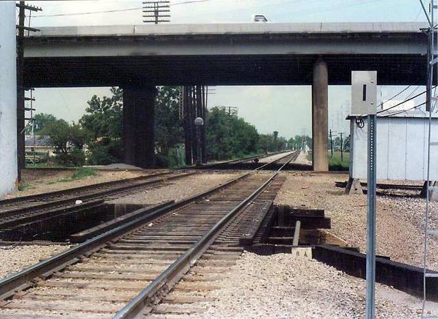
For a recent discussion of rail diamond and X crossings, I uploaded a photo of Rabbit Crossing in Houston, taken 1986 under the US59 elevated roadway. The single track crosses under the roadway at a shallow angle, crossing the double track at grade.
I have been planning to close one end of the scenic work of my layout with this sort of structure for ages (seems like forever). It’s nice to see a “how to”.
Does anyone have structure drawings or any sort of guide to the size of the different elements of the bridge please? Beam length, depth and width would be a good start… even just guideline sizes.
The best way to get good dimensionnal data is to use Google Earth and Google Street View. You find something is the picture that you know the real dimensions and then you deduced by maths others dimensions.
By exemple, on Rabbit crossng picture I would start to find the pier width. To do so, I would mesure the track width under the highway (near the shadow) since I know it is 4’-8 1/2". In fact, the pier is probably 3 feet width.
Hope this can help you. Elevated highways are always of spartan design which helps a lot. Except if you want one of those fancy 30’s and 40’s art deco bridge.