Have been through my model railway books looking for an explanation of how cab control works and should be wired up.
I am using good old DC track wiring on a small layout and have discovered over 1/2 of my locomotives don’t like the more modern electronic controllers but will run perfectly well on the 1960’s controllers that that I have.
So I need to set up 4 cabs three electronic ones and one 1960’s one that can be switched in to any of the other three sections.
NEW Fangled DCC or similar is not an option I will consider so please don’t suggest it
Can any one help with a diagram of cab control and explanation as to how it works.
There are a thousand different ways to do this but I will explain which one I have found to be the simplest.
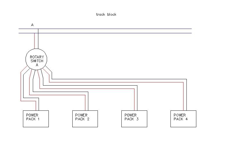
First, you need to separate your layout into blocks. Blocks are electrically isolated sections of track. Using a rotary selector switch, you can route power from any one of the power sources to the block. Each block gets it’s own selector switch.
The selector switches I use are double pole (for (+) and (-)) 6 position switches. I have 4 throttles as well. This leaves me with 2 extra positions, 1 for “off” and one for future use if needed.
The diagram below shows how to wire one block. If you have many (I will have around 20) there gets to be alot of wiring, many people are turned off by this as it looks complicated. However, it is a very repeatable thing. Just take what is in this diagram and repeat it for every block.
That should be enough to get you started but I am sure that you will have more questions. Feel free to PM me anytime (there aren’t many of us block/DC guys left). I will try to get some photos of my panel and rotary switches on here later today or tomorrow.
You would do well to buy a book on wiring a model railroad. What you are asking is complicated to answer here. Two cabs can be done with DPDT switches but four cabs needs rotary switches or something more clever. The Purdue U Club had a neat way to use modified phone plugs. I build one in the 6o’s. but it made track work look easy.
The theory is to wire all the rail blocks into a set of terminal blocks, Then wire your four controlers into a set of terminal blocks, Then connect the two sets of terminal blocks through the cab switches(rotary switches). This also presupposes a control panel than can be understood by visiting opperators. It can be done, but takes some effort to get your head around the complexities and then labeling everything so you can remember what you did. Good luck.
While the others have given you the basics of block and cab-control wiring, I’m going to discuss a little about how to set up your blocks.
First, I second the recommendation to get one of the books on DC wiring. Read it and refer to it often. DC wiring, if you weren’t raised on it, is a fairly simple acquired knowledge and skill, like soldering or prototype information.
The underlying theory of cab control is to separate your track into enough blocks so that no 2 trains are ever in the same block at the same time. Keep in mind that around an engine terminal, a train could be just one engine! A given throttle (throttle 2) is connected to the block (block A) where train X is located. Train X will be under the control of throttle 2 wherever it goes on the layout. As train X advances into another block (Block B for example), the block selector for block B is switched to throttle 2, and the block selector for block A is switched off to make it available for other trains.
Based on the preceding paragraph, each train requires 2 blocks to operate continuously - the one it is in, and the one it is about to advance into. If the block to advance into is already occuppied, the train must stop prior to the block boundary and wait for the block to clear - just like the prototype.
When you think this through, you realize that for 2 trains to follow each other in a continuous loop without repeated stopping, there need to be at least 4 blocks in the continuous loop. Which leads to rule #1 for blocks:
1) Each continuous loop or path needs a minimum of 4 blocks.
Where you have passing sidings, one train can take the main while another is stopped (or moving slowly if the siding is long enough) on the passing siding and go by the stopped train. This requires passing sidings to be separate blocks (rule #2):
I cover cab control wiring pretty thoroughly in my book, “Easy Model Railroad Wiring, Second Edition,” which is available from Kalmbach Books. It inlusdes diagrams showing how to wire for four or really any number of cabs.
I do have an ULTRA BASIC idea on DC wiring and have run one engine in steam for a very long while without really worrying about it too much the scenery is more my thing, as long as the train ran reliably I was not that bothered.
My idea of complicated was wiring a crossover so both sets of points worked together or a controled signal so a train could run through in the direction the signal was not visable to the driver when in the stop position.
But its time to get out the indoor OO scale trains again and set them up this time I want some thing better and greater contol of things without chucking out my locos, and using this new over complicated computorized stuff, that I would not know what to do with it and need a primary school computer wiz to set up for me.
Will order the Kalmbach book the next time I speak to my hobby suplier sounds like the wiring is a bit complicated and a lot of it but the principal on how it all works is reasonably simple.
Thanks for the reminder to mark the wiring with proper wire markers and draw a diagram as it goes in so that when it goes wrong I know which wires to look at, I do have the beginings of a colour coding system but its no use without the cable marking as well
The one trained visitor I get only comes around once or twice a year so he will not know the road, but will probably help with things he an I have not had a good layout building or scenery session for years
Talk about Danger two tempremental artists at work but we get what we think are good results and are not afraid to take to bad scenery or anything else with a big hammer and wrecking bar if need be to get what we think is a much better result.
No idea why but It works for us when we are working on the same railway, we seem to get a better result than when working alone.
If you don’t mind me asking, what controllers are you using and what engines don’t like them? The reason I ask is I wonder if the engines have DCC decoders in them. It has been my experience that decoders that will run on DC usually do not like any kind of pulse power. If this is the case, you might be better off removing the decoders. If they are “Dual Mode Decoders”, with a jumper for Analog or DCC,make sure they are in the Analog position.
Pace pulse controllers these are a very good Aus made controller the MR comunity over here swear by them
The locomotives are all 15 of them manufactured by Triang in the 1960’s with XO3 or XO4 motors so definitely not DCC fitted. yet they run perfectly well on the Triang controller of the same vintage
The 5 Hornby ones of a not much later vintage don’t have a problem with pulse power again definitely not DCC fitted
DCC had not been thought of, a computer would not fit in a domestic situation and TV was Black & White when these where manufactured.
Magna traction and going from giant girders to a code 100 system track where the new big things when I started with trains and I still have them not much of modern manufactured stuff on my railway since the trains still work and work well no need to replace them.
Yes this is the book to get. Pay particular attention to the concept Andy identifies as “local priority” wiring. It resolved a nagging issue I had with DC cab control. Best of all should you wish to explore DCC it covers that too. DCC starts to look awful good once you get used to operating on a layout that has it.
In addition to Andy S’s book, if you are going to use the Atlas components (and they remain an easy to find system) then the Atlas book makes a good supplement. And if you use Peco switches, i can tell you that the Peco catalog has some useful hints in it as well