Lionel O Gauge question. I am connecting remote control turnout switches on a new layout. I plan to use the constant voltage feature with the side pin (and wire) inserted into the switch, so that the switch can operate even when the train is not running. The way I read the instructions, this makes the switching power totally independent of the track power. I guess I am challenging that notion.
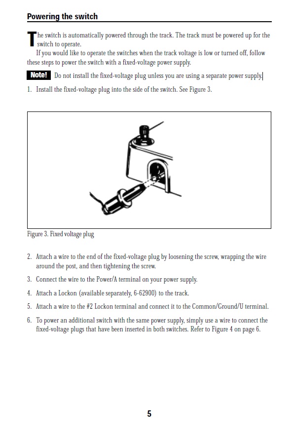
My question is this: Since I want to rely on that power independence between track and switch control, I assume that I do NOT need (or in my case want) to use any insulating pins when connecting the switches, so that the track power on the switch will continue to be variable with the track itself, while the switching operation is always available even when the train is stopped. Am I correct?
So, that depends on the turnouts. If they are non-derailing (also called auto-switching, self-correcting, or the like), then they need the insulating pins–but only on certain rails. If they don’t have those pins, then what will happen is that the turnout will chatter–in other words, both ends of the solenoid will be activated and the turnout will try to be in two positions at once, which doesn’t work very well. However, if the turnouts are not non-derailing, then they shouldn’t need the insulating pins no matter how you wire them. Obviously, you might still need the pins if you are making the turnout the juncture between two blocks, but that is a completely independent issue. Do you know whether the turnouts are non-derailing?
Wow. I had no idea. I have to say that I REALLY appreciate your helping me with this. Ok, let me provide more detail so that we can separate issue from non-issue in my case.
First, I have already decided not to run two trains or even two transformers as I am likely the only operator 90% of the time and can’t justify the expense. So, I really don’t need the insulating pins from a two-control perspective.
Second, the layout has 9 turnouts and I have had difficulty getting all of the turnouts I need. So, they are a mix of mostly new non-derailing and a few older pieces that I am not sure of, unless you can tell me how to identify them upon inspection. I thought the non-derailing was more of a design change or marketing gimmick!
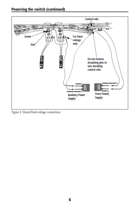
So, yes, I need to know exactly which pins to put into which rails, as what you have told me is new to me, and isn’t explained AT ALL in the instruction manual I downloaded. All it says on page 6 is to leave the nylon pins inserted. It doesn’t explain why. They come with 8 pins. Two nylon pins pre-inserted in rail ends of the switch, 1 nylon in the bag inside, and 5 steel pins in the bag. I thought that was strange, as there are of course 9 rail ends. Most track generally comes with pins at one end, so I would have expected some combination of 3 or 6 pins to finish off one end of the switch.
Finally, to restate my goal of this thread, I want to operate the switching function with constant voltage, so that I can set switches in advance of running the train. It always bugged me to have to do the just in time thing flipping track switches while the train is moving, since the track gets no power otherwise.
I am not using the supplied manual switches. I have a console planned with momentary contact, center-off DPDT switches. The second pole will control a panel light indicating the status of the turnout.
So, my concern is that there not be any cross-connection between the inserted fixed-voltage plug and the track power. The manual states with a bolded note “Do not install the fixed-voltage plug unless you are using a separate power supply.” But then, the plug only has the one (hot) connection, and you are to connect the common wire not to the “separate power supply” but to the track via lockon! This makes no sense to me. Can I not use the fixed voltage terminal on the same transformer for this? I have attached pages 5 an 6 of the manual for reference.
Oh boy.
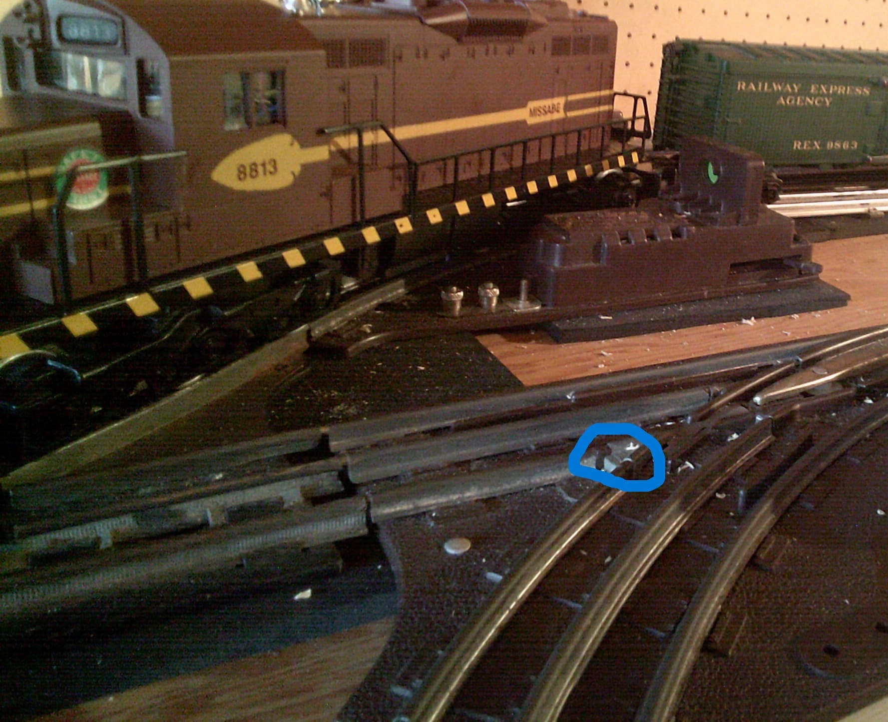
So, the non-derailing turnouts have a special rail on each turnout “leg”, as is pointed out in the diagram. Basically, said rail is isolated from the rest of the turnout by a small plastic separator. Now, that’s not really visible in those diagrams, so here’s a photo. The plastic separator is circled, of course.
Thus, it’s just those control rails which need to be insulated. So, all that makes sense so far. But then we get to the real mess. As you pointed out, not all turnouts are non-derailing. So, there are a number of ways to tell whether a turnout is non-derailing, but the easiest is to test it! Basically, you need to provide (1) positive power to the turnout and (2) touch a wire between one of the control rails and the ground connection on your power supply. If the turnout is non-derailing, then it will try to change the position it’s in to automatically provide the proper route for an oncoming train. But… some turnouts have the control rails on the inside and some on the outside. The only way to know for sure is to test both rails.
Alright, so about the cross-connection. So, the reason the track transformer and the turnout transformer are grounded together is because the turnout needs a ground connection through the track. Otherwise, the non-derailing does not work. Fortunately, any hot wires in the solenoid system should be completely isolated from the center rail. Grounding the transformers together should have no negative effects, and, in fact, can be very helpful in many cases.
Finally, may I ask how you are going to wire those DPDT switches? You may (1) need to use a slightly messy setup to make the turnout indicator light show and (2) need a time-delay relay to protect the turnouts from being burned out.
I got it, thanks! To answer your question, since the momentary contact switches would not by themselves keep the panel lights on, I will be using 12 VDC self-keeping relays to keep the lights on. When the switch is thrown in the opposite direction, the relay is released and the panel lights change to the normally-closed light (generally the main loop of the layout). So, the relay will stay locked on, but only when I have the switch in the “alternate” (less used) location. The turnout is on the other pole of the panel switch, and as such is only temporarily activated.
If they should get out of sync with the track due to the non-derailing function, I only need to do a “down-and-up” on the panel switch to get back in sync.
My follow-up question to you then would be “why the warning in the instructions about using a separate power supply?” If the hot connections (track and fixed-voltage plug) are truly kept separate, it shouldn’t matter if I use a separate transformer or the fixed-voltage output of the transformer that powers the track, right?
I’m going to assume you are asking about Lionel 022 switches for O track.
The switch motor needs power and ground to operate. By default the switch pulls power from the center rail of the track.
The outside rail of your layout is common and connects to the U terminal of the transformer and provides the common connection to the switch motor. . When you run an 022 switch from a separate power connection the action of inserting a power plug into the side of the switch shifts the power connection from the center rail to the power connection of the auxiliary transformer. This does not change the way the non-derail works and you still need the insulating pins. With the pins you are setting up an electrical circuit to the switch motor. With one side of the switch motor connected to either center rail or aux power when the train passes over the insulated rail it completes a circuit connecting ground to the other side of the switch motor causing it to energize. If you leave the pins out the switch will be continuously activated.