I just picked up the new release of the CV 150’ Truss Bridge. I’ve built a CV girder bridge before, and it was fairly easy.
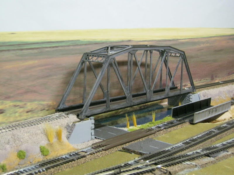
This bridge has a lot more parts, and seems kinda complicated. I’m replacing this bridge with my Atlas truss bridge. In the main layout room.
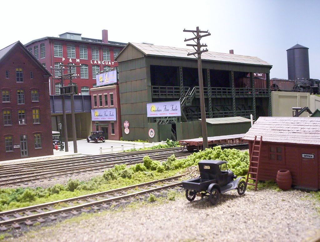
I’m redoing this entire area. With a new bigger river under the bridge, that will go to the edge of layout. I’m ripping out the lower tracks there, and there will be two new lower tracks, that will traverse the river
Old bridge:
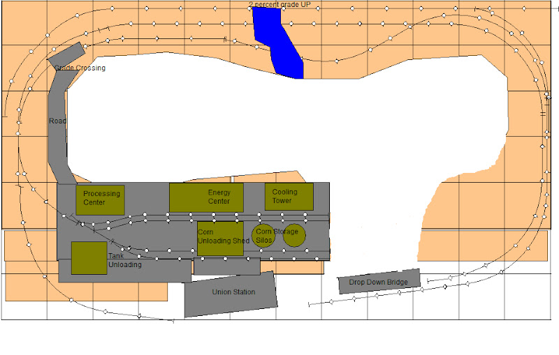
Here is the re-designed trackplan for this main layout room. This new bridge is the top track against the wall.
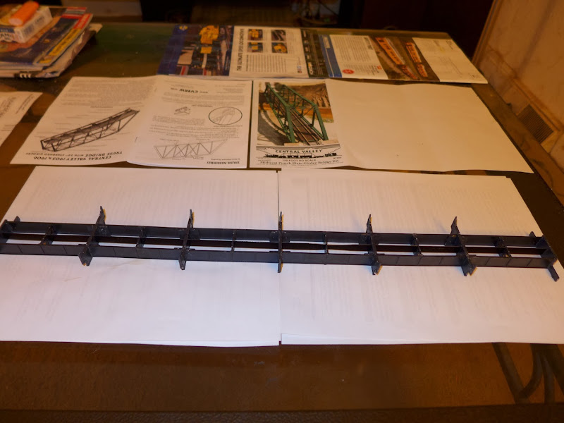
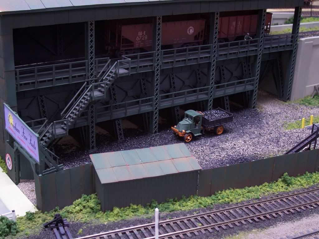
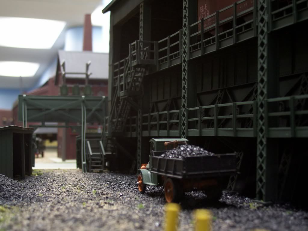
Here is the progress I made so far. I’ll keep updating this thread with progress photos.
I built the older model also, found it fun to build and good looking. Not uneasy but did take some time. The two issues I had were the string type tensioners provided, plus the rail attachment (I used code 83) requiring peening plastic bumps over the rail lower edges (web??). On the former issue, I took another’s advice here and substituted pieces of piano wire glued in. I did attach the rails via peening, but had to rework that a bit when I fiddled with the bridge. If doing again, I would glue, then peen the plastic bumps.
Does the new bridge have these issues, which are manageable?
They must have made some changes, because there are no spring tension strings. But it has two metal flat peices, that go through the middle section of the supports, you can see in my pic.
I ended up getting the Micro Engineering bridge track. So I don’t have to glue the rails in.
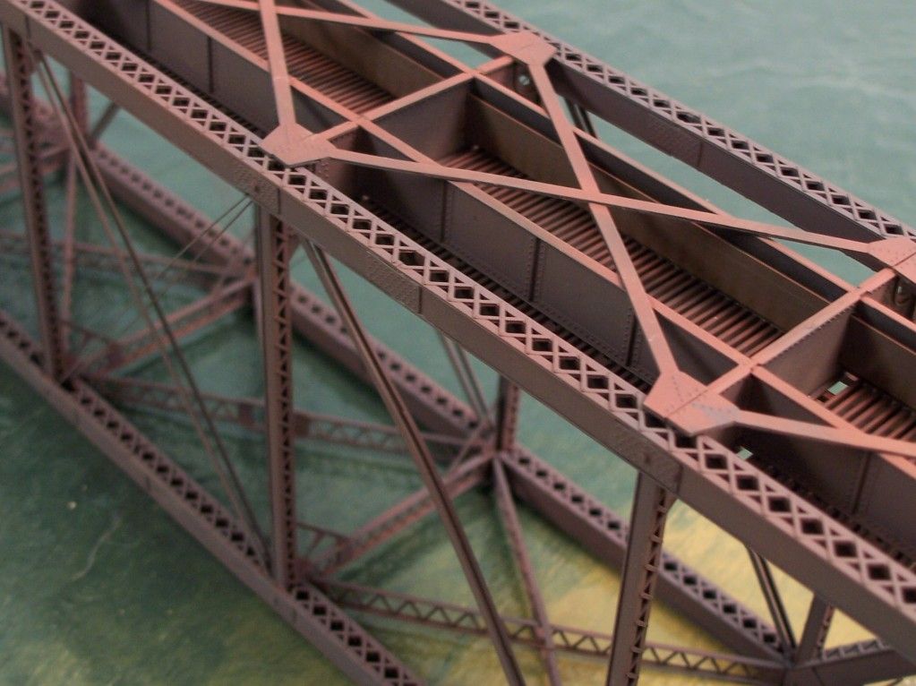
It looks like the newer version uses a different style of girders (punchplate, as opposed to the lattice-work box girders of the original version), and the photo on CV’s website shows no tension rods.
The original bridge also used flat steel strips which slipped into slots in the span’s floor structure. They keep the model bridge from sagging under load, and one of them can be seen in this photo of the bridge’s underside:
Careful - it looks to me like you have many of the girders facing the wrong directions at this point and will have problems with assembly later on. At the very least your bridge could look really odd.
Here’s the punchplate bridge on the Central Valley site. Note how all the openings in the girders face up or down in the truss assemblies. None of the openings should face the side. I’ve never seen a prototype truss with the punchplate orientation like what’s in the photo on your workbench. For that matter, the lattice or gussets would be in the same orientation.
As for difficulty of construction, if you’ve done a lot of kitbashing or scratchbuilding this kit shouldn’t present you with any big hurdles. Otherwise it could be a whole new learning experience.
OMG! See the instructions are confusing as hell. No where do they say exactly which way the box girders should be oriented. All it gives me is the top side should be solid. It doesn’t show the bottom side with the holes.
I’ll just have to flip this piece around, and it will be up against the wall anyways, so you couldn’t really tell.
Michael, call Central Valley and explain your problem.
When I was contemplating the scratch building of a lift bridge, I spoke to the fella at CV, and he indicated that they do stock extra parts for occasions just such as this.
You can probably get the necessary parts and re-do that section of the bridge.
Yes, I’d recommend doing this if possible. If you can get a kit like this assembled nicely, it can stay with you and get re-used on subsequent layouts. After putting all the necessary work into it, it might as well be the best it can be.
Rich is right, and while you can probably re-use those top members by flipping them, the diagonals on the ends which form the sides of the bridge’s portals will be too short once flipped and trimmed. Contact CV for replacement pieces, and if that fails, those girder sections, packaged, should be available separately.
Michael, if you’re not going to build the CV bridge, save the parts for scratchbuilding projects like the one shown below, and any damaged parts can be painted and then heavily weathered, to be used as a scrap load in a gondola.