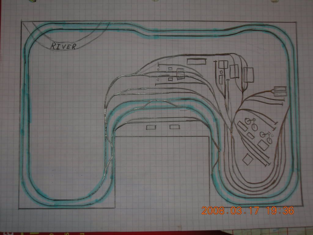
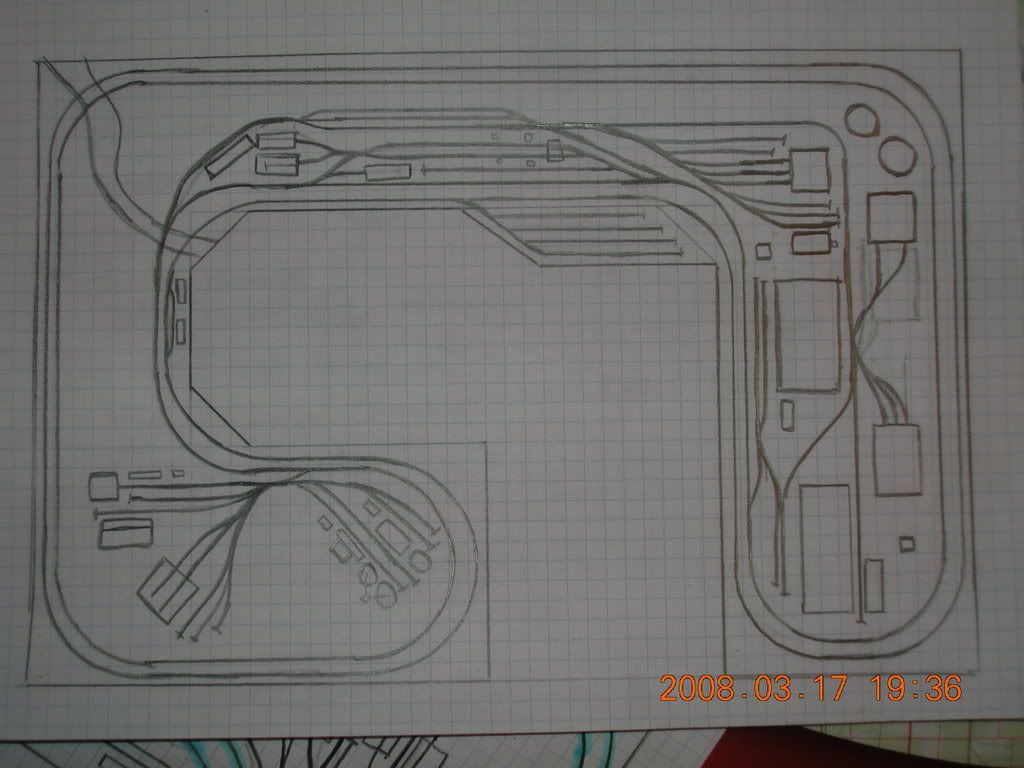
What do you think of my two layout they are both 12x8ft if it were a rectange. Which one do you like better on the first one it has an industry as in a steel mill on the left side in the blank space. The second one is my favorite, it seems to flow more. Let me know which one you like better or what you would do to change it. The layout is in N scale and all of the curves on the main line are 30" radius curves. Thanks all the help will be great.
The second design looks good, but I think they are a tad optimistic. You would do well to either download one of the free track planning software programs or buy an N-scale template at your Hobby Shop so you can get the angles of the turnouts more accurate. If such a thing existed, your turnouts are about #1s as drawn. Certainly a little tight for a Challenger.
Even tho the graph paper is 1/4" and each square is 3", the turnouts are still #1’s? I am not going to run my challenger’s through the yard just through the steam service area. My yard goats are going to be 0-8-0’s
Getting around the table to get a derailed car will be no problem I am going to be able to walk around the whole layout. The farest I would have to reach would be 2ft, a short guy can reach 2 ft.
Those so-called 30" radius curves look more like 15" radius. (Are you confusing diameter with radius?) And those turnouts are way too sharp. Why don’t you buy a few, lay them out, and see how much space they take. All previous responses are “right on.”
I posted the question about the radius early on this forum and some of the people told me to take the radius I want and divide it by 3 because that was what one square equals. So 30 divided by 3 equal 10. So they said that 10 squares would equal a 30" radius turn is this right? If they are not 30" then 15 is fine I can run challengers on 15.
By definition a turnout that diverges 1 square per 1 square of travel is a #1 turnout. Or as in the case of your drawing, a 45 degree divergence. A #4 turnout would diverge 1 square for every four squares travel or an angle of 11.25 degrees.
In other words, your drawing is a tad optimistic.
A 30" radius would form a circle 5 ft across or 20 of your squares.
I’d fix the plan before I buy my turnouts, otherwise you will end up buying four times the amount that will fit the space. In this case, it would buy that new PCM Challenger.
I understand that I need to fix the turnouts but that has already been said by everyone so far so lets get back to some comments on other parts of the layout. The yard really doesn’t need to be there I am mainly using it right now to fill space. I could just make it smaller on my layout when I make it or just plain get ride of it. Thanks so far for all of the info but I understand I dont have the turnout thing right.
Ten squares equals a 30" circle, or 30" diameter. Radius is half the diameter, so you’re looking at a 15" radius. Sounds good for N scale. Those turnouts are real “space eaters”, not to mention budget eaters. The second plan looks to have about 50, and at, let’s say $10 a pop, you’re looking at $500. That alone is enough to discourage young model railroaders. You can probably eliminate about 75% of them and still have a fun RR to run.
An “Armstrong” square is the space necessary to fit the radius curve. So, a 15" radius curve in N would result in a 16" square. Two squares, or a space 32" wide, are necessary to make a 180 degree turn with 15" radius. If your grid is at the scale of 3", it would take almost 11 grids to fit the 180-degree curve, with a 4" scale grid, it would take 8, etc… If you have a double-track mainline, to keep the inside curve within the 15" minimum, a somewhat larger “Armstrong” square is needed.
You need to take some time and study the difference between radius and diameter. Your drawing (which I edited) shows less than 18" radius curves because the benchwork is only 36" wide at the peninsula with the red lines:
Your plans look like some of my old plans, too optimistic. You are trying to fit too much in the space. The accuracy of my planing really got better after I made a template out of some sheet styrene, and now I use CAD which practically does the work of lining up track for you.
A few planning tips.
Never put in tracks without a purpose. There is no reason to waste valuable layout real estate on useless track. Make sure every track has a reason to be on your layout. Don’t use a yard to fill space. Give it a reason to be there and a useful track arrangement, otherwise it will become a big storage area.
Make sure that your track works. Make sure industry and yard leads can hold a loco and as many cars as will be switched there, preferably a few more. The same goes for runarounds. Running around one car at a time will get old fast.
Leave room for more than track. Look at the real world, the railroad takes up only a small portion of what you see. Layout packed full of track don’t look realistic because what scenery there is looks like it was crammed between tracks.
Finally, one of the most important, don’t plan bigger than the space you have. Both of the plans you drew may work, but with properly proportioned turnouts and curve radii large enough for a challenger, the layout will take much more space.
My suggestion is to get either Atlas RTS or XtrkCAD (both free) and mess around with them until your comfortable with CAD. Then planning becomes easy and accurate.
When you fix your turnouts, something else will not fit. That is why you must do all the hard figuring now…up front. Otherwise you will either have to sell all those now useless turnouts or revise the entire plan because the turnouts are the only ones that your engines will be able to use. In other words, the number of a turnout means something…not just words. The number means how far past the frog you’ll have to drive to get further away from the through route. That translates to an angle, and different angles mean different lengths of legs of track beyond them will result. Your diagram shows lots of tight angles and very tiny stubs beyond them. You may find that even your 0-8-0 won’t be of much use.
Dunno…it’s your money and plan…you make it work. [sigh]
Alright here’s my suggestion, if you’ve got room all around the layout, and a 12’x8’, and you’re 16, so duckunders aren’t that big a deal, build a full loop instead of a dogbone. Your mainline will have nice sweeping curves, and you’ll have room for a yard next to the mainline as well.
See what can be done is a full 12’x8’ loop can be built, where you duck under the layout to operate it. then you can easily use 30" radius curves, have long straightaways where the big UP articulateds can open up. A long mainline without un-needed curves also gives a better impression of the big open west.
No, no, no. 1/4" grids can represent any distance your little heart desires. If 1/4" is to represent 3 inches (1/4 foot), then 10 squares does represent 30 inches. However, a 30 inch radius curve is 60 " (5 feet) in DIAMETER. You need 20 squares to represent a 30" radius curve that describes 180 degrees of arc (i.e. a half circle). Your drawing looks more like 15" radius curves which would be 30 inches in diameter.
Thanks for all of the info so far. I will say that I am not going to use a duckunder just because I am not going to be the only one who uses it. Im sure that my family will want to use it some times. I think I am going to try one of those CAD track planing thing, I am going stick with the 2nd layout shape just move stuff around and make it fit.