Yep, I’ve been busy with my son’s H.S graduation festivities… He will be off to UCSB in the fall.
Question: What was the highest voltage used for a DC electrification and what was the trick used to make it possible? Exra credit: What was the trick used to power the auxiliaries?
Another note related to series motor field shunting/tapping: The tradional method for getting variable speed operation with a DC shunt motor was to use Ward-Leonard control, where low speeds would be constant field and variable armature voltage, and high speeds would be variable (reduced) field and constant armature voltage. Some of the early gas-electrics used Ward-Leonard control and the ASEA/EMD AEM-7’s used Ward-Leonard control implemented with thyristors.
WRT to Middleton’s Traction Classics, vol 2, I bought the book not too long after it was published from the OERM bookstore and didn’t get around to reading the chapter on the Electroliner’s until maybe a year ago. The story of the 1950 tests with the field shunting stood out, so it ws easyt to answer RME’s question.
Replying, the highest much-used voltage DC was 3300 (approximately, somewhat more than the more usual 3000) on some Russian electrifications, and some may be in use today. Usually, accessories were powered by a motor-generator producing a low voltage with battery charging capability. Some locomotives used motor-generators for traction power as well, for lower voltage to the motors, but some a motors were wound for as high as 1650 using many turns of thinner wire on both armatures and field coils with very specially designed commutators, with offset contacts allowing considerable insulation between segments. In other words, there were several paths for brushes, alternately contacting copper or brass and then hard insulation.
And I do not remember the source for what is either iinformation or misinformation; you probably know the details much better than I do.
3300 volts were used by some other countries as well. In Eastern Europe.
And I just used the Edit Button to add this comment!
While correct with the “much-used” disclaimer, there was one experimental installation with a significantly higher voltage (this is the one I’m looking for). GE had proposed this higher voltage as an option for the Milwaukee electrification. Overall system costs would have been about the same for both voltages, with the increase in locomotive costs eating up the savings in reduced feeder/substation costs.
Using an m-g set for auxiliaries was not practical at the higher voltage, so another approach was used.
The Milwaukee did up the trolley voltage to 3300 in the late 1940’s and early 50’s.
Not sure about the highest voltage, but low-voltage auxiliaries on streetcars and interurbans often used the voltage drop across the air compressor to get a voltage that could be used to charge batteries.
That’s getting close to what was done in the experimental installation, but note that the air-compressor was one of the low voltage axiliaries…
Rule of thumb for commutators on DC machines is that the potential difference between bars should not exceed 20V. That means a four pole motor wound for 1500V would need at least 300 bars in the commutator.
The equipment in the installation I’m looking for used four motors and has series/parallel control, in this case either four motors in series or two sets of two motors in series with the sets in parallel.
I do have an answer of sorts to the question: it’s shown on what’s left of this sign from the aftermath of the GE 6-pole rotary-converter experimentation…
yeh, if this was much higher than 3000 or 3300 volts, was this two wires with one positive and one negative with respect to ground?
And you can reduce the number of commutator bars having more than one ring of brushes and bars, with insulation bars between the conducting bars, as I described. The much-much wider gap for insulation allows much higher voltage, as much as 100V instead of 20V. Much higher than that and you wil get arcing as the brush leaves the conducting bar for the insulation bar. But you also have to watch the current to avoid arcing.
The installation used a single trolley wire with the track rails used for current return.
A couple of clues: The installation was done by Westinghouse and a mercury arc rectifier was used to convert AC to DC. The installtion was completed before major work was started on the main Milwaukee electrification.
A side note on 3000/3300VDC electrics - GE made a late 1969 proposal to the Milwaukee for modern 3300V C-C locomotives that had about the same continuous rating as the Little Joes. One signficant change in motor construction between 1950 and 1969 was using Kapton for insulating the armature conductors with a 30% increase in continuous current rating. The proposal said that the motor used by the internal M-G set was a 2 pole motor to allow for operation directly off 3300VDC.
Grass Lake line of Michigan United Traction Company? (Covered in Electric Railway Journal, V.XLVI, n.14 (Oct 2 1915) p.660ff) This followed internal Westinghouse testing at East Pittsburgh in 1914 all the way up to 7000V on the trolley wire. Duffy says that Machefert-Tassin, Nouvion, and Woimant, in Histoire de la Traction Electrique, mention a test between Kalamazoo and Grand Rapids at around this time with 5000V on an isolated third rail, which would be highly interesting to see… this is the famous 2400V on 80lb rail setup, but I think the reference is confusing the insulator test values with an actual traction test at that power.
Apparently the auxiliaries were run off a 150V storage-battery bank that charged in series with the four 100hp traction motors (!) which had double armatures geared to a common axle (!!) Traction current was reportedly only about 30A peak per motor, so this is less extreme than you might think.
Not one mercury-arc rectifier; three.
And to add further amusement, the car was completely compatible with normal 600V DC power…
Potter of GE apparently tested BA&P equipment at this same 5000V, but I can find nothing but anecdotal discussion of the testing.
The first reference that I saw on the Grass Lake line was in Hilton & Due’s book on Interurbans (bought my copy in 1978). There was almost no detail on the installation in the book and got my info from either a 1914 or 1915 volume of The Electric Journal. The Internet Archive has scans of those two volumes (and more) in various formats along with scans of the General Electric Review. Both the Journal and Review are good resources for the technology used in the early electrifications.
The other amzing thing about the experiment is that the equipment seemed to be pretty reliable. Unfortunately this came at the end of interurban construction, so never got past the experimental stage.
The motors for the Milwaukee electrics were tested to an equivalent of a 4500 volt trolley potential with no ill effects.
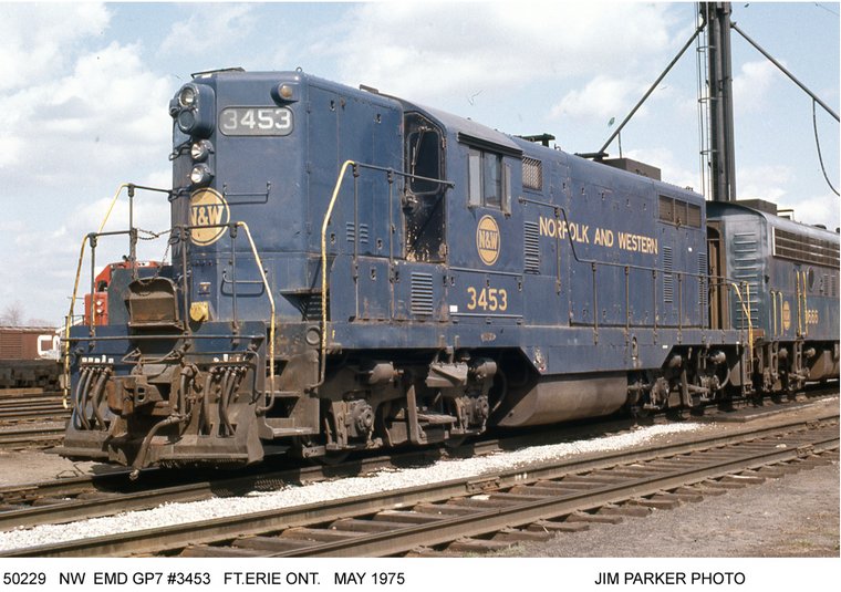
GMD-built? With a 3000-series number, it’s ex-Wabash. First GP7 in Canada? As far as I can tell it’s Wabash’s only GMD GP7 (though Wabash did have F7 sets built by GMD)
Toronto Hamilton and Buffalo #71 was the first GP7 built in Canada.
You are very close with the answer. It is GMD London built, it is ex-Wabash and was built for them, it was their only one, a sole unit among 22 F7’s but go one step further for the answer.
 In the interim, here is one. We will still await RME in the future.