Confused About How to Use Insulating Pins

I understand electricity well. No need for explanations there. My question is this: If insulating pins are meant to keep the power from flowing to the next track, and if the train’s metal wheels are designed to provide an alternate path for the electricity as they pass over the track connection, then how does the pin provide any separation?

I want to be able to run two trains with two transformers. I envision being able to power the track on the “other” side of the insulated pins with the “other” transformer. Yes, I understand about the transformers being “in phase” and that it’s ok as long as they are. But then, what transformer is controlling the train as it crosses, and how do I truly get independent control? So confused!

Welcome to the forums!
A quick question–I take it that you’re referring to O Scale three-rail. Knowing for certain could help.
So, in short, the trains are, indeed, going to bridge the track and create an electrical connection. However, if all three rails are insulated, then once the pickup rollers are both on the “dead” side, power will no longer get across. Now, let’s say that the transformer in Section 1 is set to 75% power and the transformer in Section 2 is set to 50%. What will happen is that, as the locomotive crosses the joint, it will travel at 75% speed until it has crossed sufficiently to no longer make the connection. Then it will slow down to 50%. In other words, at this point both transformers are controlling the locomotive at once. If they are, indeed, in phase, then what happens is that the track voltage will equal the highest voltage outputted by one of the transformers.
But, you asked about actually independent control. Well, that requires command control–a remote control system installed in each locomotive or else some kind of signal (usually digital) broadcasted down the track. If you want that, prepare to modify locomotives and/or buy exceedingly expensive components.

Yes, I apologize for not being clear. O Gauge Lionel. Probably not FasTrack as I don’t always have room for the roadway width.

Ok, that makes sense, thanks. So, not likely very useful on sidings, given their inherent shortness, but the insulated pins are more useful for “alternate routes”. Where a transition distance (I guess the length of the train?) can be provided. Am I right in assuming that the connection will be carried by the train itself, or only when the locomotive fully passes the junction point?

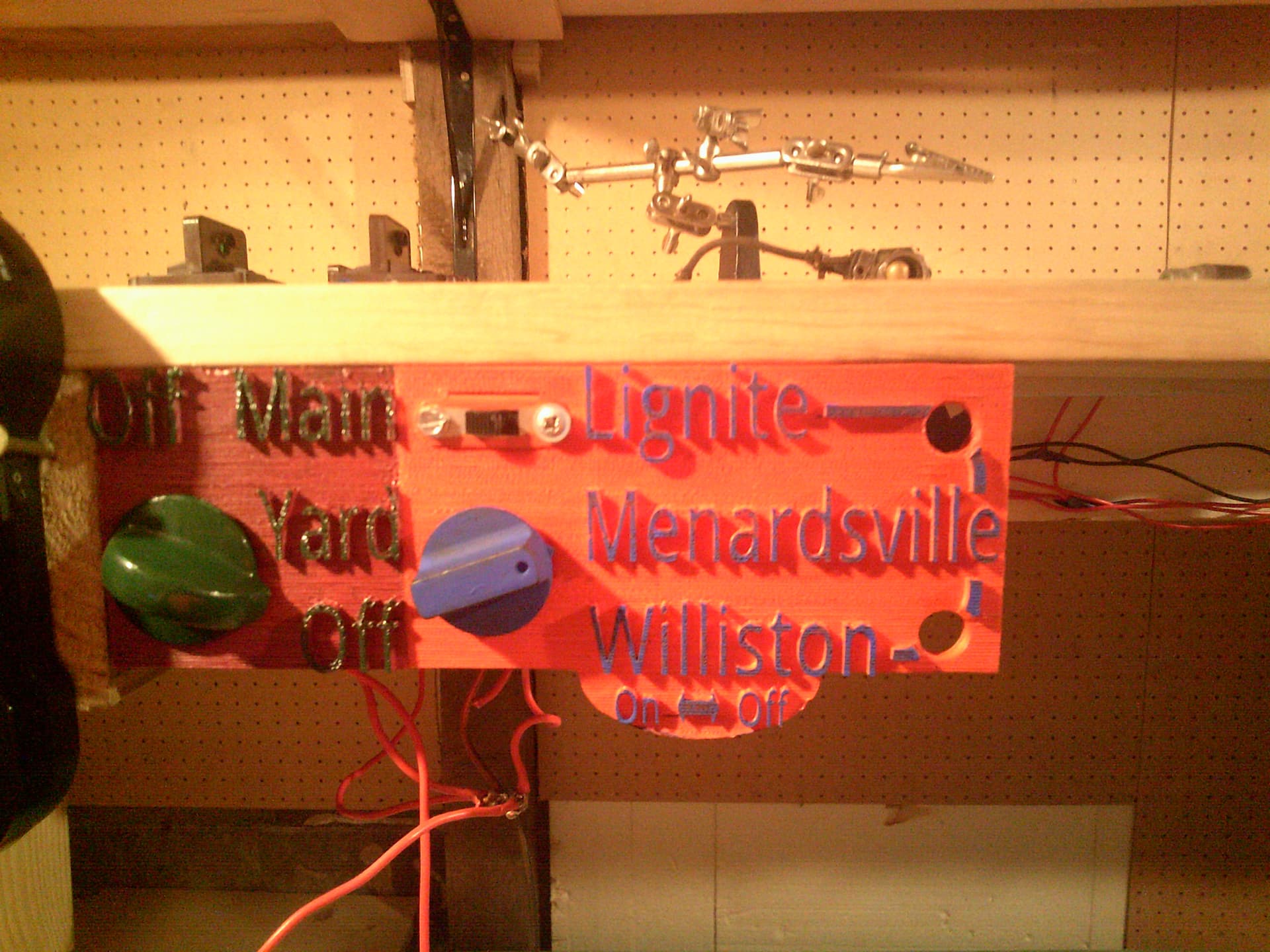
Actually, they are completely useful on sidings and otherwise. You see, the system you are thinking about has a transformer for each track block. However, many modelers prefer to have only a few transformers (say, two or three) and then use a control panel to route power to the desired blocks. “Transition blocks” aren’t really needed with this system, as you simply make sure to flip the switch before the train enters the block. As an example, here’s my control panel.

It can control if there is power from either my Type V or my 1033 transformers (the system is actually much, much more complex, but now is not the time for that lecture!). If, for example, I set the slide switch to “off” and the green (WSRR) rotary switch to “Yard”, then I am controlling the yard with the 1033 and everything else with the Type V. However, if I want to run an engine out of the yard using the 1033 and onto the other trackage in Menardsville, then I need to turn the slide switch to “on” (the blue L&M rotary switch is already in the right spot). Then, the 1033 is controlling both the yard and the Menardsville trackage and the locomotive can proceed happily between them. The Type V will still control all other blocks. If that makes perfect sense, I must have explained something incorrectly!
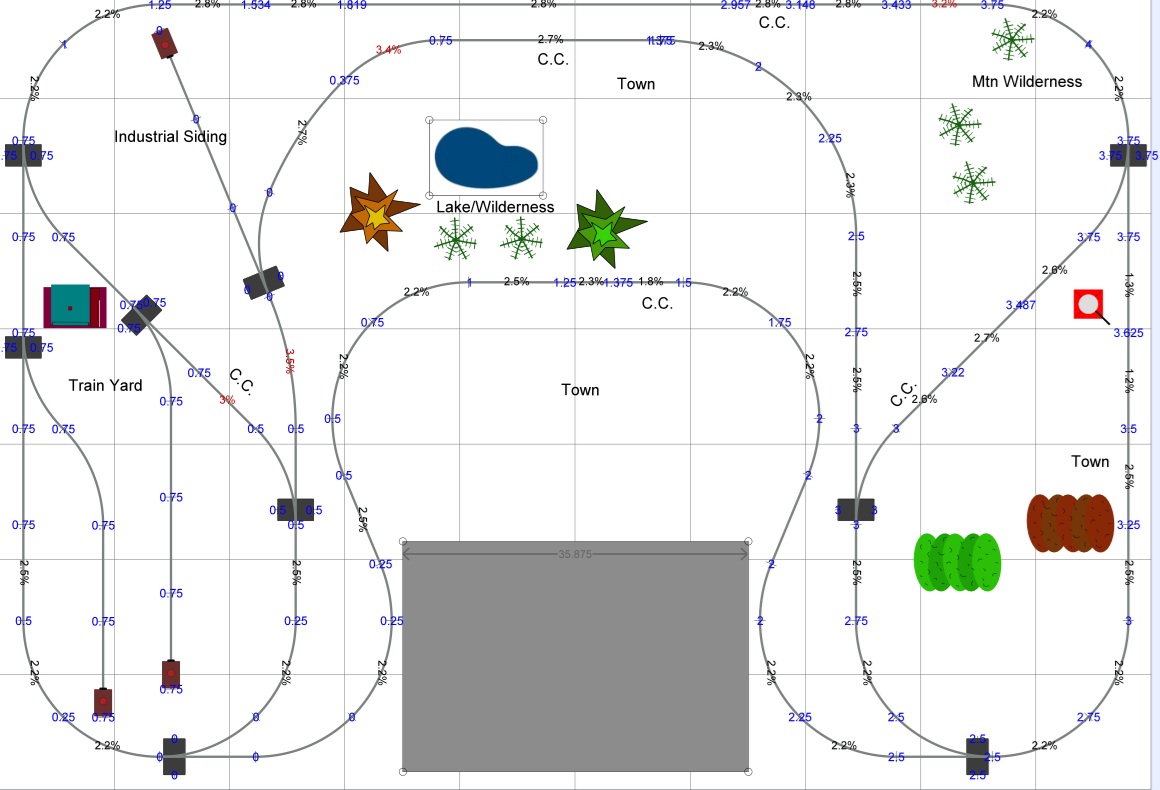
Okay, so if you simply want two or three blocks then it would be silly to design a control panel like this to control them. Simply hook up a transformer to each block and, as a train comes near the joint, try to throttle both transformers to the same approximate position. There will almost certainly be a difference, but probably not enough to cause an issue. However, except for very simple layouts, this would probably be too constraining. As such, I recommend that, if you have one, you post a track plan.
Additionally, on the topic of transition blocks, it might be difficult to wire them if you do decide to go with them. If you simply rely on power carried by the train, it will probably stall frequently. If you want to control it with the transformer, you’re gonna have a fun rat’s nest!
And, to answer your question, the train may or may not carry the connection a great length. If you insulate all the rails, then it will simply be carried the length of the locomotive (really, just the pickup rollers). Secondly, if you have any lighted cars or really anything else that has pickup rollers, it will also carry the current.

Thanks again. That makes perfect sense. Unfortunately, I am constrained to a layout of 7’ x 10’, but this is what I have been able to do with it. It has some elevation (4") and is doubly-reversible.

That’s a spectacular railroad that you’re going to have!
So, what you could do is insulate, say, every siding, and, along the main, you could basically insulate it at each turnout. What you’d then want to do is make your control panel with a diagram of the track plan and a SPDT switch at each track block. Then, hook up one terminal of the switch to one of two transformers and hook up the other terminal to the other transformer. Ground both the negative terminals to each other. This means that, with some planning and the like, you can basically run two trains at once. Another solution would be to get an SPDT switch with a center-off position, which would allow you to run two trains at once plus have as many as you like parked. If you wanted to run even more trains, you could get rotary switches and more transformers.

You are too kind! I deleted my original response as I realized that was exactly where you were going. Thanks again for the tips!

You’re welcome! Oh, another thing–if the transformers are grounded together, then you don’t need to have insulating pins on the outer rails. Also, I have a design for a remote-control throttle that can be integrated into this setup as well.

Welcome aboard nobelsw! :smiling_face: