So, I have finally gotten to my reversing loop and I am a bit confused…
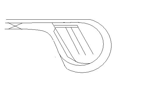
As you can see above, I have a crossover where my loop ends, so I am confused as to where to gap and place reversing sections for my autoreverser… ugh. I was wondering if any of you could help… the layout pic is not to scale, but just a picture of the general end (about 1/3) of my layout. Thanks for any help/comments…
You have two reverse loops. One nested within the other. You need to get rid of the reverse loop in the middle otherwise the connections will be messy and unreliable.
The best plan is to convert it into a simple singular reverse loop. The less connections the reverse loop has with the regular powered track, the better.
The best case would be to have a simple reverse loop connected to the regular track at one point. A simple reverse loop is just the teardrop with one turnout at the point. When the turnout is in one position, the reverse loop normal. When the turnout is in the opposite position, then the reverse loop is reversed. Any track can be placed on the reverse loop as long as it does not connect to any other regular current track, and does not form a reverse loop within the reverse loop.
While the above is not required with a reverse loop, the more connections you have, the more times you will directly short out your power supply.
Or maybe three depending on where that outside track is going.
I don’t know if I agree with that. Careful placement of an autoreverser might allow one to work for both loops. Here is just one of serveral possibilities. If you put the reversing gaps on the bottom track either including the first turnout of the crossover or just past its points. Put a set of gaps on the yard lead track where it branches from the loop. And finally put a set of gaps on the loop track just past the turnout where the other side of the yard lead branches off. This isolated section would be where to put the auto reverser.
I think one loop is enough, but you do need to isolate it at 3 points. At the top, where the turnout goes into the yard, isolate both tracks at the frog end of the turnout. At the bottom, again where the turnout goes into the yard, isolate only the path not going into the yard, again at the frog end of the turnout.
I don’t think you can do a reversal without going through this path. As long as the loop is long enough for your trains, I think this will work. In this case, the entire yard is part of the reverse loop, but that’s not a problem. In fact, if you get a PS-REV from Tony’s Trains or something similar, you will also get circuit-breaker protection which will help electrically isolate the yard from the rest of your layout.
Thanks for all the input. Not where I would have guessed to put them… hmmm. How/where (books or site) did you guys learn about autoreversers…?
As for removing the outer loop, well, that is where my “high” main line comes down and meets the inner loop (branch line). Not really an option… anyways, thanks for all the help…
Or at least a part of that path. Don’t forget the double crossover.
I don’t like a yard being on an automatic reverser and the lead for the yard not be. That could mean that when one was drilling the yard it could be flipping the reverser with every single move.
I think that this configuration might leave the reversing section too short. A reversing section needs to be at least as long as the longest train that will be run through it.
So it is not really a reversing loop at all. In that case it is not involved. past the turnout where it branches from the reversing loop.
The yard is not on the autoreverser. I would guess the yard to accessed from the top not the bottom. Maybe Brian could shed some light on his operations??
I understand why you would want a reversing unit as long as the longest engine latch-up, but why are you concerned about the whole train. Are you concerned that metal wheels will short across the insulated joints?
At our club we always switch our track once the engine crosses insulator leaving the rest of the train crossing reversed polarity. Often the train is longer than the length of the isolated track. Then again, we have very few metal wheels on the layout.
Sure… so here is my total track plan. Sorry it is not truly to scale… I am old fashioned and still draw it out on graph paper (LOL… and I was a robotics programmer at one time…hahahha). Anyways, all the curves are 26" with a 30" easement. The curves off the mainline into the roundhouse are 22-24"… Grade varies from 2-3.5%. Anyways, here is the FULL plan.
The outside (left and upper) is a high line that comes down at the two ends… As you can see I have a linear brachline that will interact with the mainline at the yard. I think the name for the overall plan is a sort of folded dogbone, but I am a relative re-newbie… Hope this helps. I did dig out my DCC book and I am still confused where to place the autoreverser, but getting closer…
OK, I’m estimating that your layout is about 24 feet wide by 16 feet high, as the picture is drawn. You’re going to have trouble reaching to the back of the corners unless your arms are about 6 feet long. But for this discussion, you’ve got a reverse loop on the left side, too. Don’t forget that one.
Now that I see the whole thing, it looks like you do indeed have two nested reverse loops on the right, plus a single one on the left. Like it or not, the right-side yard is part of the inner of the nested loops, and should be on that reverser circuit. The x-crossover in the middle makes the whole outer loop a possible reverse loop as well.
I have sections in the middle that “pop” or lift out so I can access the track… no problems there… As I stated, things are not to scale, so the room size is lik 16 x 12 or so…
Good point about the left being a reverse loop…I just decided to add this double crossover. Before that, there was no reverse on the left (at least I don’t think so). Hmmmm… I really don’t want the yard part of the actually area that get’s it’s polarity reversed. Does it really have to be part of it? Hmmm…
Crud…I just realized I posted a bit of an error in my track plan…here is the true plan now. Sorry. This is why I usually draw by hand [:(] Lost it in transcription…
Yes, lighted cabooses, passenger trains, metal wheels, wheels with resistance, and helper locomotives. The real issue I guess isn’t the length of the train but rather the chance that two things would be simultaniously telling the reverser to flip the opposite direction. There is the most probablity of this happening with two electrically conducting things in the same train.
Correct for the location you put the gaps. My yard comment was directed toward the suggestion that MisterBeasley had made. It gets confusing sometime with so many ideas on the table simultaniously.
Ok well actually good. That means the original part you posted is the only important part. I see no further “reversing” sections in the rest of the layout.
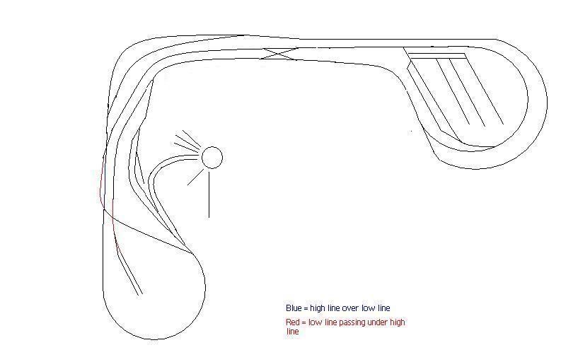
Here is a picture that might help us talk about this.
My original suggestion was where the two red dots are and the one yellow dot by the crossover. But now, knowing where the outside loop goes, I would extend that to include the other yellow dot on that outside curve.
If one used the two red dots and the blue dot, that would achieve what some of the others were saying but with a slightly longer reversing section, and it would leave the yard and its lead in the same block.
Actually which ever one you connect the reversing unit to. Nothing says that you couldn’t put the reverser on the main and hard wire the loop and still the same results[;)]
Seriously, the reverser should go on the block starting at the red dot near the top just past the yard turnoff. It doesn’t matter which one of our suggestions you eventually take for where that block ends, that will always be the starting point and the section that flips polarity.
Thanks alot, Texas. You think after 14 years of school and training I could figure this out, but man this is WAY outta my field. Kinda feels like the first time I “sparked” (aka defibrillated) a guy… I was thinking “Oh SH%$ I hope this works!” Anyways, your help is much appreciated.