I bought an 8 amp MRC booster for my layout. Can I take the wires from my Base unit and connect them to the booster or do I need to split the layout and have the track connected from the booster and the base unit.
I just went through the same experience. I too thought it was a “booster” and that it would connect to the output of my Prodigy Advance 2. Not so.
It needs to feed a separate section of track. I ended up dividing my layout with a small section that makes up an engine terminal with the 3.5 amp Prodigy and the rest of the layout with the “booster”. Works fine.
I don’t think it should be called a “booster”. That implies it goes on the output of the basic unit which isn’t correct, though it does sort of act as a slave of the basic unit.
Here’s a sheet on how to hook it up. Sorry, the sheet is not super clear unto itself.
https://www.modelrectifier.com/v/vspfiles/resources/dcc/0001521-8%20amp%20booster.pdf
Deane
Thank you, I agree. I was told I could just take the wires from the base unit and put them in the booster. I will split it. My layout is quite large and is basically a large oval,it will take some figuring how to split it without getting feedback from somewhere.
A little bit of the consideration has to do with where you’ll be running things that need more current capability.
In my situation, I wanted to run several multple units of 4 and 5 engines each. That was too heavy for the 3.5 amp Prodigy. That’s why I assigned the “booster” to the main layout and the 3.5 amp Prodigy to an area that wouldn’t be running more than an engine or two at one time. The Prodigy basically powers my turntable and the roundhouse stall tracks. Since the only stall track that is active is the one the turntable is pointed to, only one engine there will be drawing current. That’s the way I divided mine, you’ll need to puzzle out how to put the current capability where you want it.
To take this a bit further, I think MRC’s vision was that it would work well for clubs that would likely have a number of different activities going on at once involving engines so they visualized dividing a layout into blocks and having a “booster” in each block. Just another way to do it.
I will comment that the unit works great and after I got over my confusion at the beginning, all has gone well. Frankly, I don’t even remember its part of the system.
It’s seems to have a very good circuit breaker. If you get a short on the track, it seems to cycle the circuit breaker about 1 per second until it’s cleared. I probalby wouldn’t let that go on any longer than I had to for fear of doing some damage. Better to look for the short with an ohm meter.
Why would you think this unit should not be called a booster? It performs exactly that funtion, it apmplifies, or boosts, the low level signal coming in over the RJ45 jack to the full power DCC signal that goes to the track. Just liek most every other booster from other manufacturers, though some do take the full track power from the primary system as input - but that just means you need to leave the primary system disconnected from any track because a short there will short the signal feeding the booster and shut down the reast of the layotu as well. On most systems, the low power signal that is used to interconnect the command station and boosters operates independently of the track output of the base systems - most brands have a base system that is both command station and booster in one physical box, but the two functions are independent of one another.
Hooking two power packs in parallel to get more power to the rails didn’t work for DC, or for AC Lionel trains - and it doesn’t work for DCC either. There’s also a bit of a (false) perception that DCC needs more power. A motor only decoder draws very little power, the loco’s motor is still teh biggest current draw. A sound decoder may use a bit more to power the amplifier, but even then - most modern locos with sound draw less power than a 30 year old Athearn Blue Box loco. And we happily put 2 or 3 of those on a traina nd ran them with those DC power packs that sometimes claimed a 2 or 2.5 amp rating but upon closer inspection were more like 1.5 amps tops. So why do we think we need 8 amp DCC boosters all over the place?
–Randy
Very good Randy!
My locomotives average under 400ma with sound on. Even the ones with dual Canon EN22 motors draw less than 700ma with sound. A pair of E7 diesels pulling a dozen overweight passenger cars up my 3½% grades draws less than 800ma with two sound decoders, and that also includes the passenger car lighting.
Mel

My Model Railroad
http://melvineperry.blogspot.com/
Bakersfield, California
I’m beginning to realize that ag
You should find one fo the Stewart/Bowser Baldwin switchers. Withotu a decoder, it drew about 50ma running, maybe less, on level track with no train. ANd 10ma of that was probably the LED headlight. From full throttle on DC it woudl coast halfway around a 4x8 loop when the power was cut, the motor generating enough current to keep the LED lit the whole time. Seems like the same Cannon motors in those that I’ve seen in other locos, but none of my others are quite that good. I’ve had an awful lot, sound and non sound, all in the same power district with no problems, and that’s with the breaker set to 2 amps. I looked like Lucy in the chocolate factory but I even had 12 locos all moving with the 2.5 amps rated output of my Zephyr system. Half of them had sound.
–Randy
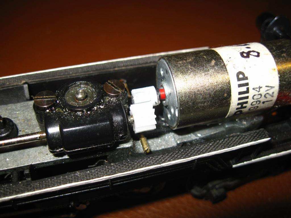
I have a Rivarossi Cab Forward that I just installed a Philips 9904 12 volt 8600 RPM motor with a Mel 2:1 gear reduction that draws just under 60ma at about 50MPH scale. I added 10 ounces of weight to the shell. I haven’t run it on my layout yet only a test track but it looks like a real winner.
Mel
My Model Railroad
http://melvineperry.blogspot.com/
Bakersfield, California
So are you guys saying I don’t need to split My Layout, just use the booster because 8 amps is more than enough power?
Well that all depends on how big your layotu is and how many trains you are trying to run at the same time. But for most people runnign trains alone, the 3.5 amps of the base system ‘should’ be enough.
I would not under any circumstances apply 8 amps directly to the track for HO or smaller scales. I would definitely look in to breakign the layout into sections with individual circuit breakers, because 8 amps at 15 volts is plenty to melt parts of locomotives.
–Randy
It is basically a large oval, the mainline is double track 200’ long each, sidings and other track make it approx 660’ long. I recentle added a long branch of about 100’ with a reverse loop at the end.
It is an odd shape about 25’ x 24’
There are always about 20 engines on the layout but the most I had moving at once is 10.
After I added the branch it seemed like I needed more power, it was now failing the quarter test, hence the booster. To take the wires from the base unit and put them in the booster is very easy. To split the layout in 2 not so easy. Everything is soldered together, 14 gauge wires run under the layout and splits in 3 directions. There multible #18 feeders about every 4’ to every track on up to 3 levels. Because it is a continuous loop it can feed from many places. The directions show power to the track from both the base unit and the booster with each section isolated
Just thinking out loud: Is that because there aren’t enough feeders or the bus gauge should be # 12? Honestly I don’t know but someone might.
You raise an interesting question, can you just use the booster without feeding a track with the basic unit. I haven’t tried that, so I don’t know. I’d try and get an answer from MRC customer service. One way to look at it is that if you have the 3.5 amp basic section connected to a separate block, and there are no engines on the track, you effecively don’t have it connected anyway. Seems like that’s saying it’s acceptable.
So far as 8 amps is concerned, I can only say that’s the way I’m doing it. Double track main line in a large oval nearly the size of yours. I’ve had plenty of shorts doing my set up phase. Plenty of passenger cars getting derailed, engines derailed, each event creates a short that trips the “booster” curcuit breaker. Nothing got welded, haven’t seen any sparks, nothing other than the clicking of the circuit breaker going off and on until I clear the issue.
I’m not recommending that you do any specific thing, just sharing what I have done with the same components and have had no issues. If 8 amps was too much, why would MRC have it on the market and be selling them?
As they say, your mileage may vary.[:)]
I’m not an expert but I would imagine that larger scales would draw more amperage than HO or N, so 8 AMPs would cover those bases. On the other hand, the Prodigy Advanced² base unit, maxes out at 3.5, and I’ve found that to be more than enough to meet the needs of my 16’ x 23’ layout.
Boris
Yes, larger scale locos draw a LOT more power than our puny little HO and N locos. Not all, but definitely some - I think there is at least one dual motor Atlas O loco that draws nearly 8 amps at stall all by itself.
Failing the wuarter test doesn’t mean you need a booster, it means the wiring is inadewuate - the bus line is too long/not thick enough, there aren’t enough feeders, etc. There is a point you reach that the layout is just too big that no matter where you locate the system, the bus wires end up being longer than recommended - in those cases, a booster is often necessary, but not because there is not enough power available. In such a case you would NOT put the booster right next to the system unit, you would locate the booster closer to the section it will power - that’s why boosters connect via their own connections and not right off the track power. That low power signal can go longer distances without falling below the minimum needed to trigger the booster.
- amps isn;t too much. It;s too much right tot he track without some sort of protection. No one section of an HO layout should ever need 8 amps all to itself, that’s why you use circuit breakers to divide the layout into multple sections, each limited to some more reasonable current level. Each of those sections needs to be planned out so that all your locos aren;t in one section at the same time. So ways to divide up a layout would be east main, west main, yard, engine terminal, and industrial switching area. The 8 amp booster would feed 5 circuit breakers in this example, each one might be set to say 2.5 or 3 amps, since the number of running locos in each of those areas wouldn;t need much more than that. A full 8 amps can and will melt plastic.
This is unfortunately another one of those areas where MRC’s “simple” instructions fall down on the job. The “simple” instructions are enough to get you going, but there’s a lot more to it which they simply do
Thank you Deane for your suggestions, they really helped.
I contacted MRC and they said I could do it either way, just taking the track wires and putting into the booster or I could do it with the Prodigy Advance and have two sections. They said some people break their layouts into districts as Randy said.
I could divide the layout but would require considerable work, so I tried connecting it first to just the booster and it works much better than before, it passes the quarter test everywhere.
I got a reply from MRC within minutes. I like this system, particularily the handheld controllers.
Thanks for all the replies.