I am planning my control panel for part of my layout. I have attached the fascia board (3/16" tempered hardboard) and plan to paint it flat black. I also plan to have LEDs and toggle switches for turnout control as well as LEDs to indicate train occupency of a single track hidden staging spur and hidden track under a mountain. I plan to mark the layout schematic in white.
Does anyone have any suggestions for marking the layout on the fascia? Stencil with paint, white tape, etc.?
Draw what you want in any paint or drawing program. Get it the right size and color with all the clever text you want. Print it out and glue it to your board. Then cover the whole thing with any good clear plastic. Then drill the holes for switches and lights. Put a nice boarder around it and you have a good looking panel.
I would suggest the white tape, available from Micro-Mark or at your local auto parts store for striping on autos. In the event you change your trackwork, you can take the tape off and rearrange it. If you choose to paint, I would suggest a paint marker, looks like a magic marker, and a good ruler. A lot easier than trying to cut a stencil.
Are you putting your switch controls and occupancy indicators on the schematic in their location?
The old fashioned and permanent way to make a panel is to paint the panel white (or yellow, or orange…whatever you want the stripes to be colored). Then, using 1/4" masking tape (available at CarQuest or another autobody store, or even 3M direct), lay down your lines. Then paint the whole panel black. Remove the masking tape, and now you have colored lines on a black panel. These will never peel, fall off, or discolor over the years like certain kinds of tape will.
To label a panel, my club has been using Brother P-Touch labels and sealing them on the panel with a clear coat finish. The old way was to use dry transfers, but these didn’t last under any kind of wear.
I am in the process of making several control panels now. I suggest that you paint the area white (or whatever light colored paint that you like). Let it dry for a day or two. I use the tape from MicroMark and make a schematic of the track plan with the tape. I then paint over the entire area with flat black. The next day, I remove the tape and I am ready to go. I use lettering from Office Depot to label the towns, industries and of course, number the turnouts (all of my wiring is bundled under the layout with the turnout number on several different spaces on the wires. This makes trouble shooting problems easier to back track. I agree with Paul A. Cutler with respect to sealing the lettering with a clear coat finish.
I have 1/8" facia board around my layout. What I use is a sheet of paper with my diagram sandwiched between to pieces of lexan ( plexiglass) that I got at Lowes. I then drill holes for the LED’s and switches. I use Lexan (even though it is more expensive) because acrylic has a tendency to crack if not drilled slowly and precisely. I simply use MS Powerpoint to design my diagram. If a ever need to change the diagram (ie add a track) I simply unscrew the panel. pull out the old diagram and put the new one in and drill the new hole.
My control panels (2 finished, more to go) are based on thick yellow styrene salvaged from obsolete store displays. The track schematic is laid out with Dymo tape, with the electrical section data punched in before installation. The colors vary, so the beginnings and ends of basic and extended electrical sections are obvious to train operators.
Most controls and indicator lamps are set in the track lines. Controls for semaphore signals are positioned in the appropriate positions related to the tracks they control, and the handles are painted in the appropriate patterns for distant, home and start blades. (The Tomikawa Tani Tetsudo is operated on the staff and ticket system, with electrical simulation of manual interlocking - the system used on the prototype branch line that inspired that portion of my modeling.)
When I build the panels for the visible part of the JNR, which will have color light signals, the control panels will have equivalent color LEDs in the appropriate locations.
Thanks for all the helpful suggestions and photos to match.
Since my fascia is 7 feet long and the control panel part will be toward the middle, I would like to have a seamless transition from neat, smooth hardboard to the control panel and back. Some mentioned sealing or fixing the artwork/paint/tape of the control panel. How is this done without spraying or applying a sealer over the entire board so it will look uniform?
When I made the big panel for the yard, I used the old tried and true method of painting the hardboard white, applying pinstriping tape and/or drafting tape, then painting over everything with a dark green colour. I applied the dark green rather heavily with a brush. When it was dry I removed the tape. I needed to have the track lines different colours so I painted over the white lines with an artist’s brush and the colours I wanted. Because the green paint was applied rather thickly, it left little ridges along the edges when the tape was removed and those ridges contained the coloured paint nicely, making for neat lines.
I also have some small control panels in various places for local use. For those, I bought some 8" X 10" sheets of some kind of clear acrylic at Home Depot and cut them to size. I painted the back side white with a spray can of the kind of paint used on plastic lawn furniture and put the track diagram on the unpainted side with pinstriping tape. I found some problems with this. Even though I sprayed a couple of coats of clear finish over the tape, it has a tendancy to curl up at the ends where it’s cut for block boundaries and switches and LEDs. I did the cutting before spraying the clear finish but that didn’t seal the ends everywhere. Other than that, the small panels look good.
For labels, I used clear (transparent) address labels in my inkjet printer, cut them out close to the lettering, and stuck them on. The label doesn’t completely disappear, but it’s good enough.
Just some thoughts on my experiences. Nice panels, BTW, nbroder.
This handsome panel is on Seth Neumann’s layout modeling Niles Canyon where the WP and SP (now just UP) had lines connecting interior California to San Francisco Bay. The photo includes reflections on the clear-plastic panel, including my belly.
This panel just controls the wye-junction portion of the layout. The rest of the layout is operated using controls within the fascia along the route. I haven’t spoken to Seth about why this location has a fancy panel, but I imagine it was because on the prototype the railroad had an interlocking control tower here. However, on the prototype and not modeled here, the WP mainline crossed two leg’s of SP’s wye, and the tail of the wye went north to begin the San Ramon Branch rather than to Pleasanton.
I second the label maker concept, I have a Dymo label maker that can make text labels up to 1/2’ in multiple colors and fonts. They also have clear labels with different colored labels we used it at the club to re-do a few of the control panels as the transfer lettering was worn off in spots. We put a thin piece of clear acetate over the finished panel. Rather then remove all the toggles we just cut the holes in the acetate jsut big enough to clear them.
I am using Black Delrin plastic with 1/8" white automotive pin stripe. I used black because my LED indicators are more pronounced than on a white board,which I used on my last layout. I Googled images of “Model Railroad Control Panels” and found some interesting and awesome control panels.
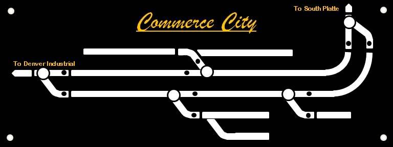
Just wanted to give you an update as to what one of my finished panels looked like. I posted earlier about sandwiching a diagram between two pieces of Lexan. I you cut out the right size hole you could make it flush with the rest of the facia.
I have found this method simple and takes about a hour to print, drill and place the electronic hardware. I finished all my control panels in a weekend.
This panel is 6"x8" and 1/4" thick. I use push buttons and 3 mm LED’s for the turnouts.
I designed the diagram in Powerpoint and printed it on a color laser printer at work
My club used 1/8" clear lexan to make the panels. they laid out the track diagrams on the “back” side of the lexan with 1/4" tape, then sprayed the whole back side a medium gray. After the paint dried, they peeled the tape off and brush-painted the track lines with various colors according to the type of track (mainline, siding, interchange, etc.). Once that was completely dry, they drilled out the holes for the various switches and pushbuttons.