though I have read and looked at many track layouts. I still have not seen much of control panel layouts.
Being new at this hobby and getting into the design stages of my track, which i have found and modified to suit. but now would like to know where to go to find such diagrams.
there might have been something written before, but being on a rural phone line. my connection is very slow so I don’t go to far down the list.
thanks for help in the past weeks also. guys.
Welcome Paul. After I had my track plan, I started drawing control panel plans on squared paper. When I had what I wanted I drew it on Microsoft WORD. I then printed it on a color printer and laminated it between Plexiglas and Masonite. The thinkness was determined by the switches I was installing.
Note, The size sort of depends on whether DC or DCC and how many panel controls you want for all the extras. I included a cutout for my Humpyard Switch Levers.
Note. You probably will not get it right the first time, so have fun and fix it later. If you wait for perfection to start, you may never get started. If yu have not yet, check Bob G.'s thread on “Unplugged”
I my layout is a loop, so I cut the plan at a convient point and made a point to point panel:
To save space I recessed the throttles into panel. I used pinstriping from the hobby shop and lettering from the office supply store for the graphics.
Here’s one of my control panels (the only one right now, but several more will be added):
The “M” near turnouts at Laurel mean “manual.” These are controled by Caboose Industries’ high ground throws. The toggles at other switches control my tortoise switch machines.
When I redesign my control panel, it will have all the mainline block switches in the top row (Row 1), the branchline block switches in the second row (Row 2), turnout control in the third row (Row 3) and switches to control structure lighting blocks in the fourth row (Row 4)
I’m making small control panels for the layout. I drew the Diagrams up in Corel Draw X3 then I added siding names and what way the track goes to cities on the layout. I then went to Home Depot and got 1/4" plexiglass (its called safety glass in some areas) I cut that out to 4" x 8"'s, i next went to Menards and picked up some nice solid oak strips 1/2"X 2"X 3" which I will router out 1/8 or so and make a groove for the plexi glass to sit in and make a really nice control panel. I use Minitronics mini DPDT switches. Sorry I have no pictures of these but I can invision how nice they will look. I went with thicker plexi cause of the bumping situation dont need them to crack etc.
Here are some of my panels, I needed three seperate panels to run the layout with 4 different packs. It is all DC and you can run with any pack on any line at anytime.
as you can see the layout is still undergoing construction so dont mind the mess and the panels still need to be labeled.
The frame is just scrap 2X8s (actually, old stair treads that led from the basement to outdoors) trimmed to make a sloping panel and grooved to support the panel face:
The face is just a sheet of plain white paper with the graphics added using Adobe Photoshop and MS Paint, sandwiched between two sheets of lexan, all of which slide into the frame grooves. The graphics:
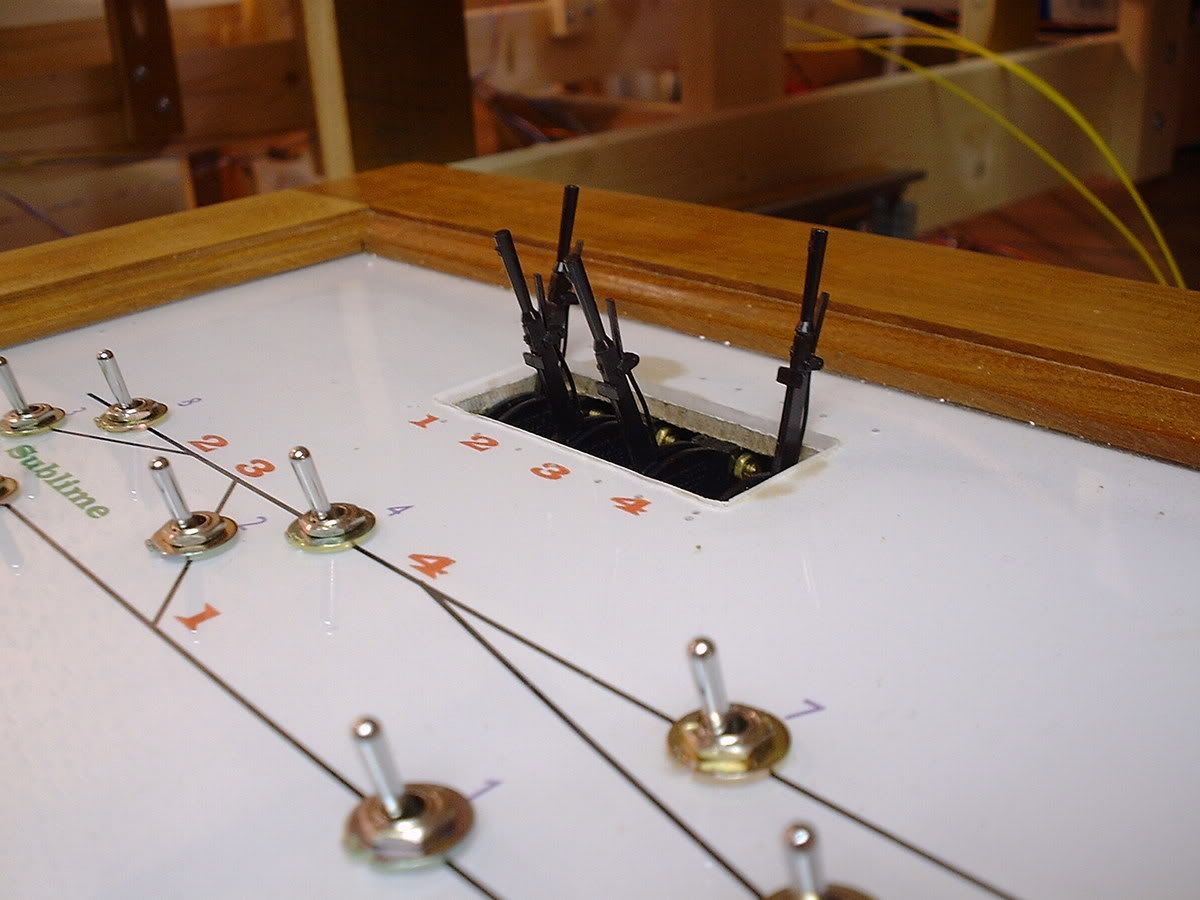
Here we’re looking at the back of the panel with the back frame removed. This view is nearly edge-on to the panel proper. The switches are SPDT submini toggles. They and the terminal strips are from Digi-key. The panel is roughly the size of a sheet of letter paper - 8 1/2 X 11 inches. I hadn’t started wiring it yet when I took this shot:
The costs of the panel and frame themselves were almost nothing, save for the lexan sheets, which totaled about $10. I got those at Lowes. Electrical components were the most expensive part, of course. The panel sits on one of those wheeled, chromed-wire kitchen carts so I can roll it around a bit:
The cabling which ties the panel to the layout looks like this:
The panel controls 16 turnouts. Once the powered turntable
Here is the Castle Tower control panel from my layout. The tower operator controls the current mainline and the staging yard.
I used red and yellow buttons and LEDs for turnouts, green buttons and turnouts for signals, and blue lights (not yet working) for occupancy detectors in the hidden staging yard. While it may not be completely prototypical, I tried to make the controls logical so that a visiting operator could run it. (Everyone knows that you don’t actually build a layout for yourself–you build it for all your friends to come over and operate. [:D])
Here’s what I’m planning. Along the entire layout, on the black facia (that extends allmost all the way to the floor), I would paint a rough shetch of the track (and all the turnouts) in white and place a toggle switch over the turnout locations to operate them. For the controls, I would mount the permanant controller in one spot and all the auxillery throttles in pockets (they would be wireless) at misc. locations on the facia, along with the infared recievers. I’m hoping to get all this done within the next few months, so stay tuned for pics!
Refer to the April 2006 issue of Model Railroader, the article entitled “Bilding a Sense of Reality”, page 77, picture number 5 to get a rough idea of what I’m talking about.
Only advice I can think of from experience is this. Abosolutely make sure you have written down someplace what wire [colour etc] goes where and does what.
Second, make sure it is big enough to work in. I made one small once [as per instructions] and found my big hands were not able to connect things properly and it became a lesson in frustration. It doesn’t have to be huge, just comfortable at least.
Third, I would take my time and do it slowly on paper a number of times to make sure I have planned ahead. While it does not all need to be done at once [it can grow as you put in new spurs etc.], it should be future proof. Another possibility of course is to have several control panels. For instance, one for a yard, another for the mainline, one for the service area, and maybe only one switch for a turnout on the other end of the layout.
The ideas are endless, but justmake sure you write it all down so you can trouble shoot it all later. Stephen
I hate to be contrary here, but if you use modern walkaround layout design and turnout controls mounted on the fascia, you rarely even need a control panel.
Any controls you need are on your throttle or DCC command unit, and no control panel will be necessary on the main layout.
The one exception may be some yards with lots of powered turnout throws like a staging yard. I do have a control panel on my HO Siskiyou Line to throw the turnouts in staging, but that’s it:
(click to enlarge)
I made this panel by drawing a simple track schematic on my PC in PowerPoint and then printed it out on a laser printer and glued the page to a piece of 1/4" masonite cut to size. Then I mounted the panel on a box made of 1x2s and put it in place along my staging yard. I drilled 1/4" holes and mounted toggle switches in it to control the tortoise switch machines.