I’d like to create a track plan schematic for my layout but I don’t know how to do so. Can anyone suggest any reading material or website that will help me understand how to create a schematic? I found several examples in Track Planning for Realistic Operation by John Armstrong, but I still don’t understand how to change my track plan to a schematic.
Are you talking a schematic to use for dispatching, a schematic to use for control panels, or one for use with wiring diagrams? I guess I am not understanding what there is not to understand. Draw a long line for the main line. Follow map protocal and put east (or north for a N-S rail line) to the right. Start at one end and draw a short parallel line representing each passing siding in the appropriate order. Add lines in the configuration of the industries in each of the towns, label as desired and your done… Our club’s dispatching schematic was too long for a single line so we broke it into three separate lines on the same page. It shows the location of stations so passenger trains can be spotted on the main or siding as appropriate in each town.
Do you have a link to your railroad track plan somewhere?
I am wanting to create a schematic to help develop the timetable operations for my layout. I know that this probably should have been done before I started laying track, but I’ve managed to break all of the rules so far…so to answer your question, it would be for dispatching, I think.
Where I was confused was representing the curves as a straight line…does everything just get drawn out and straightened on the schematic? Here’s a jpeg of my trackplan…
That’s pretty much the idea. You are just trying to represent the connections and distances between them. If you have any of the compilations of Armstrong plans look at the layout diagram and the schematic of one of the simpler plans side by side for a while and you’ll catch on, I think.
Basically, yes. The curves are not represented on a dispatching/timetable schematic for the most part. A schematic is mainly intended to set up places for trains to meet, etc. Therefore, whether or not there are curves does not really matter. Dispatching a curvy railroad and a straight railroad is really not different, except that a dispatcher needs to keep in mind the time it takes at track speed to get from one place to another. Most schematics hardly even represent the mainline. A schematic might only represent the mainline between two sidings with enough space to write a train number.
Generally, yes, although you may show some curves to show how the tracks connect for continuous loop configurations, reversing connections, etc. I’ve found the easiest way is just to start at some point and work my way around the layout.
Usually not all the industry spurs and such are shown and the distances need not be porportional, instead, they may be expanded or contracted as needed for clarity. (Edit: if you’re most interested in timing for a timetable, proportional spacing may be a little more important)
For example, here is John Armstrong’s Pennsylvania and Potomac from 101 Track Plans.
To unwind it into a schematic, I picked a convenient point (the track in the tunnel at the right), and began drawing it out.
Note that the reversing connection is very obvious in the schematic, even though the final result doesn’t look like the track plan. The schematic is a logical view of connections, not anything like a recreation of the track plan itself.
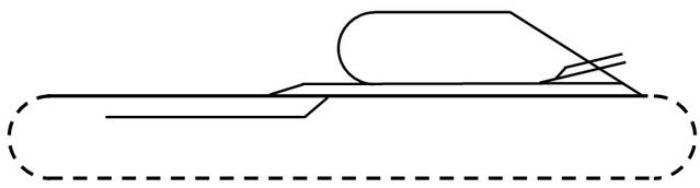
Okay, with help from TrainmanTy, I think I got it figured out. Here’s my rendition - I ran out of room so instead of a loop on the left end, I created a square box.
Don Z.
Edit: Now I need to figure out how to make it big enough to actually read.