I need to build a rather long bridge, part of which will have a 32 1/2" radius curve. I’m looking at using 4 Micro Engineering 60’ Viaduct Tower kits which are essentially two 30’ deck girder sections put together. Can I install a 32 1/2" curve on those bridge sections or do I need to widen them?
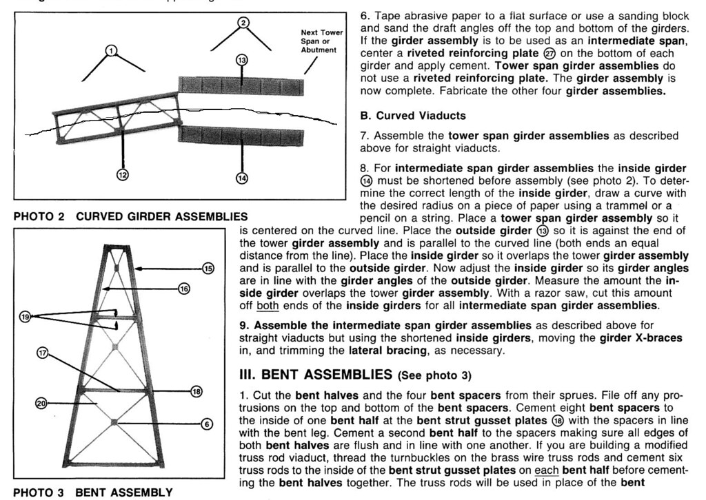
I crudely penciled in the center line as it barely shows in the instruction photo.
I finally built my viaduct in a straight run but I did experiment with making it curved. I don’t see a need to widen the girders. My bridge kits came with ME bridge ties which were wide enough to cover the tops of the girders if curved, but they were short (rail length) and would have been a pain to try to curve them and join them. Yes, I see ME makes a 36" length of bridge track [Y]
They make a longer section of flex bridge track and I would go that route. You might have to epoxy the bridge ties to the girder since the ties are “slippery engineering plastic” Walthers Goo would probably work well, too.
I built my steel viaduct over twenty years ago. It was tedious but worth it. Very detailed.
I have the ME instructions somewhere but I haven’t found them yet. Doctorwayne was kind enough to send them to me a while ago.
Tedious is OK. I just modified about 40 Atlas and Peco turnouts to add jumpers between the point rails and the closure rails, and between the closure rails and the stock rails, as per Allan Gartner’s recommendations. That was tedious, and I only have 30 or so more to do. Actually, I plan on running a seminar on how to modify the turnouts for anyone in the club who is interested. It will be interesting to see how many turnouts get destroyed in the process![swg] I figure I will have to start with basic soldering techniques before the members actually start applying heat to the turnouts. Should be fun! I love teaching.
My scratch/bash bridge has ME bridge track…1pc is 3ft. You have to add the code 70 rail to the ties and there are detail spikes that the track sits into. I would make My curve first held in place with metal pins to the radius desired and then glue the guard rail in place,that way it will hold the radius. Then you also have to glue the timbers in place. Each one is about roughly 3’’ long. I used Zap-A-Gap Medium Ca for the rail and the wood ties, which are styrene. I rough-up both surfaces before applying CA. After it was all complete, I did not touch it for 24hrs. Everything dried extremely strong like it was one piece. I then air brushed the whole track with Floquil tie/rail brown. I’m sure You can do it on a curved section.
Images may be clicked on for larger view…
The bridge flex track also comes with two platforms used in a trestle with fire barrels, which are hollow made from Pewter. I used those for scrape metal in a shop area, Yellow drum…
I have done this and it is easy as long as one side will not be seen as the rivits sometimes will not line up where they would normally be. I asembled the girder bridge and then chop sawed it with a hobby cutoff saw, you could also use a regular hobby saw but damage is more likely. Would include pic but photo hosting site is persona non grata.
I don’t have a photo of the backside of the tall bridge (have one of the low bridge, though), but my method was to shorten the spans on the inside of the curve, usually at a vertical stiffener, and leave the ones on the normally-unseen side as-is. If you need to make a cut where the vertical stiffener at an end of the girder is removed, use a strip of styrene to fabricate a replacement on the end of the shortened span.
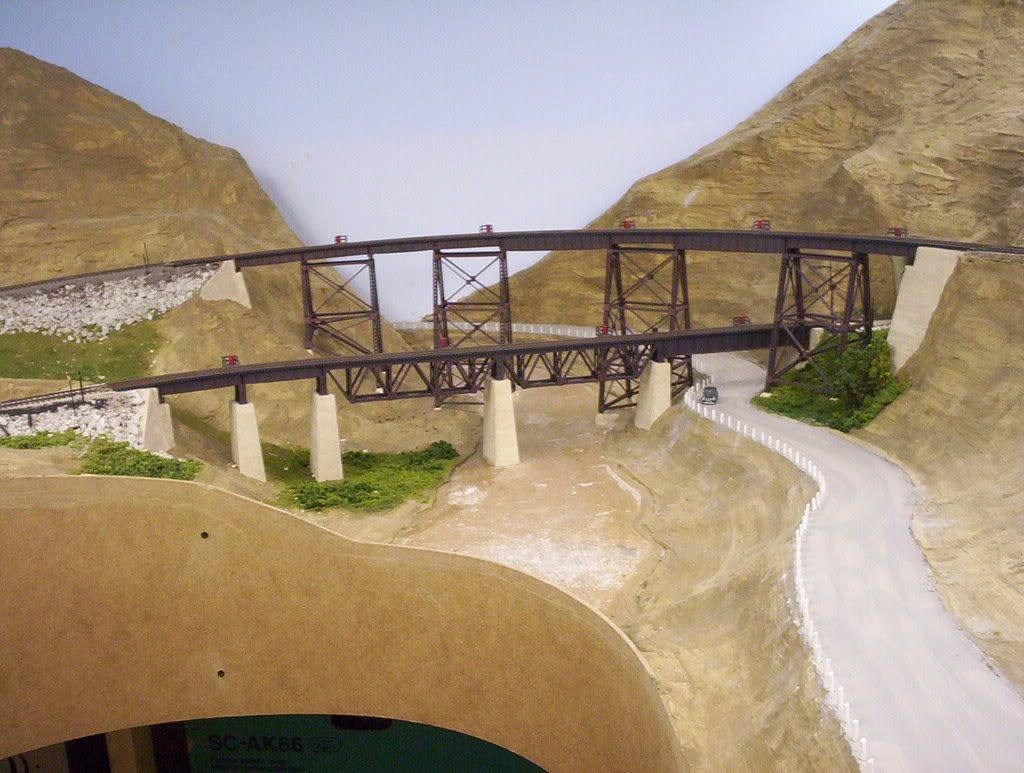
I built all of the bridges on the layout by cutting out the plywood strip of roadbed over the rivers, then turning them upside-down on the workbench and building the bridge and support piers, upside-down, atop the plywood. That ensured that the bridges all fit properly in place. All five major bridges on the layout are curved.
I’m finishing a 26"R viaduct and will be doing a 30"R next. I was really concerned about the curve but it was never a problem, other things were.
No towers, just bents, and used deck girder PLATES, not the full bridge KITS. Black foam spacers inside (can’t see thru the ME bridge ties, or bottom). Also rough-cut the inner girders which are hard to see. Biggest challenge was mixing 50’L and 70’L girders to get different footer locations below the bridge. The 70’L girders are taller than the 50’ so I had to add an I-beam under it.
Railings were hard to do but the outer walkway gave me overhang clearance for P cars. These railings are not prototypical, and the board gaps were for my wife’s fear of heights, lol.
Getting it level (hope to get super-elevation) is my current challenge. It’s so long that I’m having a tough time getting measurements. I’m using a Micro Mark digital level and a truck with a bubble level. Neither of those is working well - they show level at points along the way, but I can see it’s not right. My next attempt will be a long carpenter level spanning each end with a metal bar pivoting from the middle. I’ll move the bar along the rails to make sure everything is at the same elevation relative to the end points. Then I’ll use the digital meter with a .020 shim (with the level set relative to sea level).
The bents are currently hanging since it was built upside down. I have a plaster mold for stone piers under the bents. I dropped a string “plumb bob” and had to adjust for where the piers ended up next to the dock. A 3D puzzle far worse than the bridge sections.
Also you can see I’m supporting it with clamped boards. The clamp is hard to adjust so I’m making a screw feed support (turn a bolt to raise and lower precisely).
I think that only one of mine is level, while the other four are on grades. If you want superelevation, displace the base of the centre support (or as close to the centre of the entire span as you can get) towards the outside of the curve. The bridge and track will form their own vertical easements into and out of the curve and you need only support the piers accordingly.
Great tip. Thanks. I was having problems with the Micro Mark digital level (my fault not the tools) because I was setting zero on nearby tracks that I assumed where zero. Then I saw the note on the front of the tool “hold for SEA LEVEL” (can’t believe I never saw it). That’s the real datum to use, and with 0.020" superelevation it’s important. I went back to other tracks and NONE were at zero.
Dave, when I built the ME viaduct for the club layout, the base for the bridge section was actually run on spline, that I cut out and transfered the “footprint” to a piece of 1/4" plywood for use as a template for building. The track for bridge started staight and eased into a 42" superelevated curve. the template made mitering and fitting of the 30 and 50 foot sections quite easy. To get the angles and geometry right and easy to deal with, I transfered the template to cardboard to allow drawing out the mitered angles of all the bridge sections. Another hint for acurate bridge track bending, curve the track against the template, then minor changes can be done before gluing to girders.
Note: haven’t posted in some time and need to retrieve photobucket pics or to another host site. Pics would be nice, drwayne has quite a few good ones to work from.
We are doing basically the same thing with the sub roadbed except ours is 3/4" plywood with Homasote on top. However, I hadn’t thought of transferring the bridge pattern to cardboard to help calculate the mitering angles. Thanks for that suggestion.
I have a question regarding your method for superelevation. Are the piers/towers actually built on a slight angle or are they straight up and down? Sorry, I’m not quite getting the picture in my mind.
Well, I did mine with the piers at a slight angle - I don’t know if it’s prototypical or not, but chose that method mainly because it worked so well where the track is on risers.
For the riser-supported track, I had all of the risers clamped to the benchwork crossmembers, with a pencil line on each denoting the proper height to keep the rise of the grade constant. I then selected the riser closest to the middle of the curve, and after placing a locomotive on the curve, carefully removed all of the clamps. I then lifted that centre riser to approximately its proper height, and pushed its bottom end towards the outside of the curve. When the angle of superelevation “looked right” on the locomotive, I aligned the inside end of the pencil line on the riser with the top of its joist, and re-clamped it in place.
Because all of the other risers were not fixed to the benchwork, the 3/4" plywood roadbed (about 2" wide) flexed torsionally when that centre riser’s bottom end was pushed out, but the amount of cant decreased as the distance from the centre riser increased , automatically creating easements into and out of the superelevation.
All that was left to do was to lift each riser, in-turn and without changing its newly created angle of deflection, until the inside end of its pencil line was was even with the top of the joist to which it was to be fastened. It’s actually easier to do than it is to explain.